Abnormal display – FEC DSP1500 (SAN3) User Manual
Page 118
PAGE 8-2
enFORCE
Operation Manual
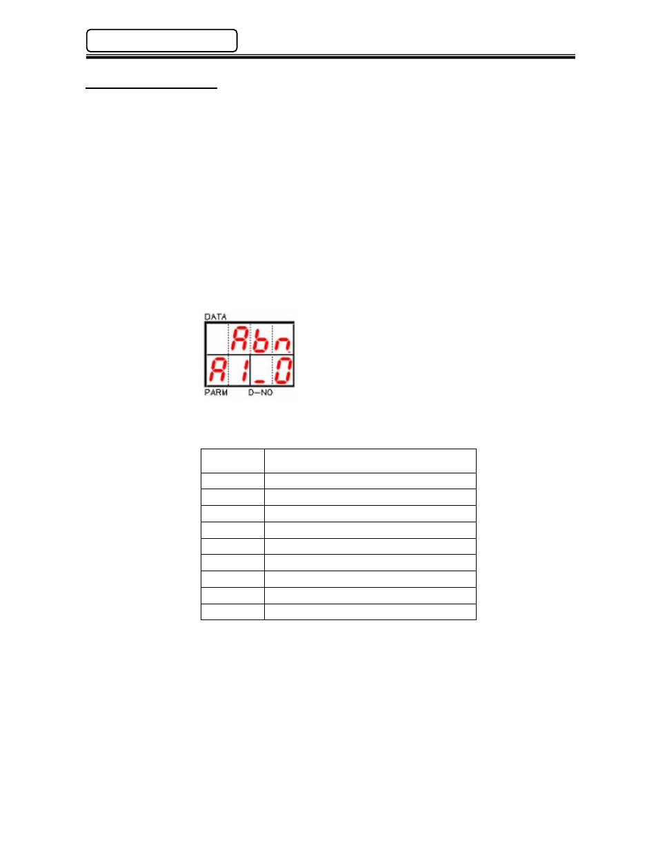
8.1 Abnormal Display
When an abnormal condition is detected by the system, the affected press stops and lights the
ABNORMAL LED. For ease of troubleshooting the nature of the abnormal, the system provides an
abnormal code in the [PARM] display and an abnormal sub-code in the [D-NO] display.
• Abnormal code display.
When an Abnormal condition occurs (ABNORMAL LED is lit), the display mode will automatically
change to the STATUS mode. (If the display is not in the STATUS mode, depress the MODE
button until a blinking “A” appears in the [PARM] display area) A code number appears at the
right side of the blinking character. This code refers to some specific type of failure detailed in
the tables shown in the following sections.
• Abnormal Sub-code display.
The number shown at the most right position in the [D-NO] display area is a sub-code that can
be used in conjunction with the Abnormal failure code to further narrow down the cause of the
fault. See the following sections.
The main Abnormal codes are:
ABNORMAL
CODE
DESCRIPTION
1 Load
Cell
Error.
2
Offset Load Error.
3
Tool EEPROM error.
4 System
Memory
Error.
5
Servo Amplifier Reply Error.
6 Servo
Type
Mismatch
Error.
7 Internal
Error.
8
Servo Amplifier Error.
9 Parameter
Error.
Abnormal sub-codes and specific actions for troubleshooting are detailed in the following
section.
Chapter 8: Troubleshooting