Motor power-resolver connections – FEC DSP1500 (SAN3) User Manual
Page 39
PAGE 4-7
enFORCE
Operation Manual
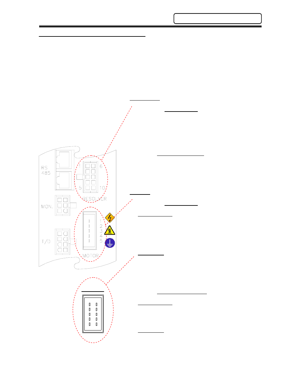
4.5 Motor Power-Resolver Connections
The motor connector provides control power to the motor.
The resolver connector handles the signals that define the rotation of the motor. The controller
provides a signal to the winding of the rotor. As the rotor spins, two sets of stators, electrically
shifted 90 degrees, generate a sine wave and a cosine wave signal. Both signals are processed by
the controller to define position and speed of the motor.
The signals for the motor and resolver are contained in one cable. See Section 4.13 and
Appendix A for connecting cable part numbers and specifications.
RESOLVER
Wiring Chart
1: (R1) Rotor
6: (R2) Rotor
2: (S2) Stator
7: (S4) Stator
3: (S1) Stator
8: (S3) Stator
4: Not Used
9: Shield
5: Not Used
10: Not Used
Mating Connector
Manufacture:
Molex
Housing Part No.:
39-01-2105
Contact Part No.:
39-00-0047 (Qty.-7)
MOTOR
Wiring Chart
SAN3-24S, 40S
1: Frame Ground
2: Not Used
3: W Phase
4: V Phase
5: U Phase
SAN3-120S (Shown Below)
1: Frame Ground
6: Frame Ground
2: Not Used
7: Not Used
3: W Phase
8: W Phase
4: V Phase
9: V Phase
5: U Phase
10: U Phase
Mating Connectors
SAN3-24S, 40S
Manufacture:
AMP
Housing Part No.:
1-178288-5
Contact Part No.:
1-175218-3 (Qty.-4)
SAN3-120S
Manufacture:
AMP
Housing Part No.:
1-178289-5
Contact Part No.:
1-175218-3 (Qty.-8)
Chapter 4: System Setup and Wiring
1
2
3
4
5
B A
SAN3-120