San unit specifications – FEC DSP1500 (SAN3) User Manual
Page 17
PAGE 2-3
enFORCE
Operation Manual
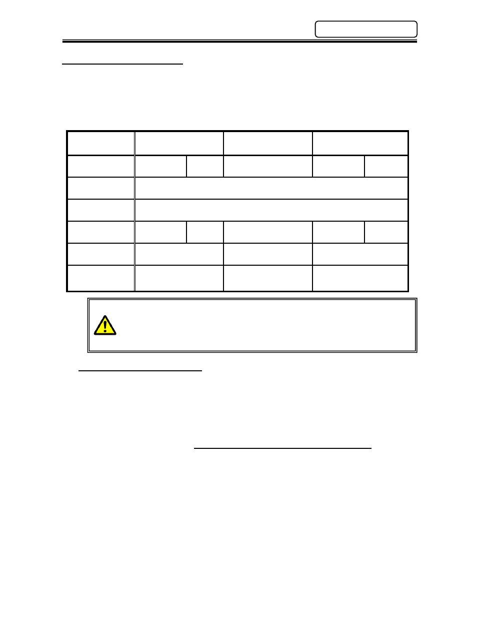
2.2 SAN Unit Specifications
CPU:
32 bit RISC (Reduced Instruction Set CPU)
Data Communication:
RS485 (2 Ports) – 1 for DSP User Console Software
Parameter / Firmware Storage:
Flash ROM
SAN Unit
Type
SAN3 - 24S
SAN3 - 40S
SAN3 – 120S
Motor Type
RM1
RM2
RM3
RM4H
RM5
(B)
SAN Unit Input
Power
180~242VAC
, 3φ
SAN Unit
Frequency
50/60HZ
MAX. POWER
OUTPUT
60W
80W
200W
1500W
3000W
IN-RUSH
CURRENT
18A
38.6A
116.4A
SAN POWER
CONSUMPTION
18W
IDLE
31W
IN CYCLE
18W
IDLE
3
9
W
IN CYCLE
18W
IDLE
109
W
IN CYCLE
After powering down wait at least 5 seconds (1 minute recommended) before
powering up again. If the equipment is powered “ON” and “OFF” repeatedly
without this delay, the in-rush current circuit will stop the unit from functioning.
If this happens it may take up to five minutes before the unit will power up
again.
2.2.1 Duty Cycle Calculation
Duty Cycle is rated as a percentage of the time the motor is running to the overall cycle time of
the machine. This is an important factor in determining overload protection for servo amplifiers
and motors as it directly relates to the amount of power or heat dissipation of the motor / servo
package. The rated duty cycle for the
enFORCE
system is calculated as follows:
Duty Cycle Percentage (%) =
Tool Pressing Time x 100
Total Cycle Time (Tool Pressing + Tool Waiting)
Duty cycle ratings vary between tools. As a general rule, however, it should not exceed 60%. If
duty cycles remain above 60% for extended periods, a “Servo Amplifier Error / Overload” will
result (see Abnormal Code 8-10). Protection for high duty cycle is a standard feature of the
servo amplifier to prevent servo or motor damage.
Chapter 2: Specifications