Rear panel – Sanyo DSR-M814 User Manual
Page 9
8
NAMES AND FUNCTIONS OF PARTS
INTR
OD
UCTI
O
N
19. USB port ( P.27, P.63)
Used to connect a CompactFlash card reader or
CD-R/RW drive. You can copy settings (CompactFlash
card only) and recorded videos.
20. [REC/STOP] button and indicator
Starts normal recording. Indicator lights during recording.
During recording, pressing the button for at least 3
seconds stops recording and turns off the indicator.
21. LOCK/REMOTE indicator ( P.26, P.58)
Lights when operations have been locked by the key
lock or security lock setting.
If an operation button is pressed when the security lock
is set, a buzzer sounds. The key lock cannot be set
during playback.
The indicator flashes at 4 times per second when there is
a network connection, and flashes at 1 time per second
when there is a network connection while locked.
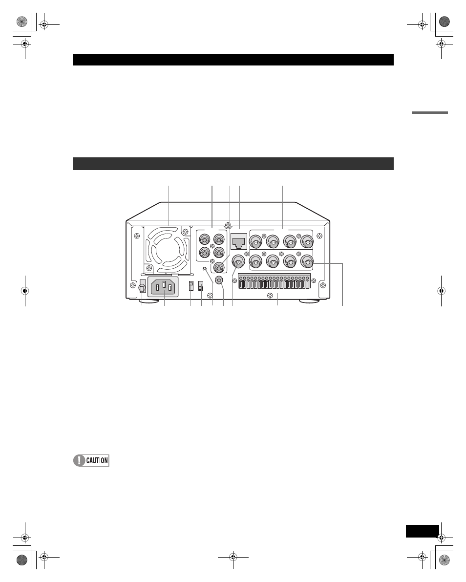
1. FAN
2. AUDIO IN terminals (4 channels)
3. AUDIO OUT terminal
4. LAN terminal ( P.59)
5. VIDEO IN terminals (4 channels)
6. Power cord holder
Secure the power cord to the holder using the supplied
cord tie. ( P.11)
7. AC INLET
AC power input terminal (3-core)
8. TV SYSTEM selector switch
Used to select between NTSC and PAL systems for the
camera input and monitor output connected to the digital
video recorder.
Disconnect the power and then connect it again after
selecting NTSC or PAL.
9. RS-485 TERMINATE switch
Turns RS-485 termination ON/OFF.
10. ALL RESET switch
Resets the clock and camera titles setting and restarts
the unit. (Menu settings are maintained)
11. MIC IN terminal
12. VIDEO MONITOR OUT terminal
Output terminal that displays quad screen on a single
monitor.
13. Control and alarm terminals
Used to connect other digital video recorders and
external devices, such as a system controller, remote
control, and alarm sensors. ( P.66, P.67)
14. VIDEO OUT terminals (4 channels)
Terminals for output of individual video channels directly
to the monitor.
Rear panel
AUDIO
IN
3
4
1
2
OUT
LAN
1
1 2 3 4 5 6 7 8 9 10 11 12 13 14 15 16 17 18 19
2
3
4
1
2
3
4
IN
OUT
MONITOR OUT
VIDEO
ALL
RESET
ON
NTSC
PAL
TV SYSTEM
RS-485
TERMINATE
OFF
MIC IN
AC IN
1
3
2
5
6
7
12
13
14
4
9
8
10 11
e00_VDH_M814.book Page 8 Thursday, October 28, 2004 9:59 AM