Series recording connections, Control terminal specifications, 2nd dvr 1st dvr to 3rd dvr – Sanyo DSR-M814 User Manual
Page 68
CONTROL TERMINAL SPECIFICATIONS
67
AP
PENDIX
The connections for a remote control circuit are shown
below. Connect the remote control to the REMOTE terminal
and C (ground) terminal.
Use a resistance of 1/10 ohms or more and with a D
ranking (precision 0.5% or finer).
SW16 operates the same as the [REC/STOP] button on the
digital video recorder. When the switch is turned on while
not recording, recording begins. When the switch is kept on
for 2 seconds or more while recording, recording is
stopped.
Alarm sensors can be connected to the ALARM IN 1 to 4
terminals and C (ground) terminal.
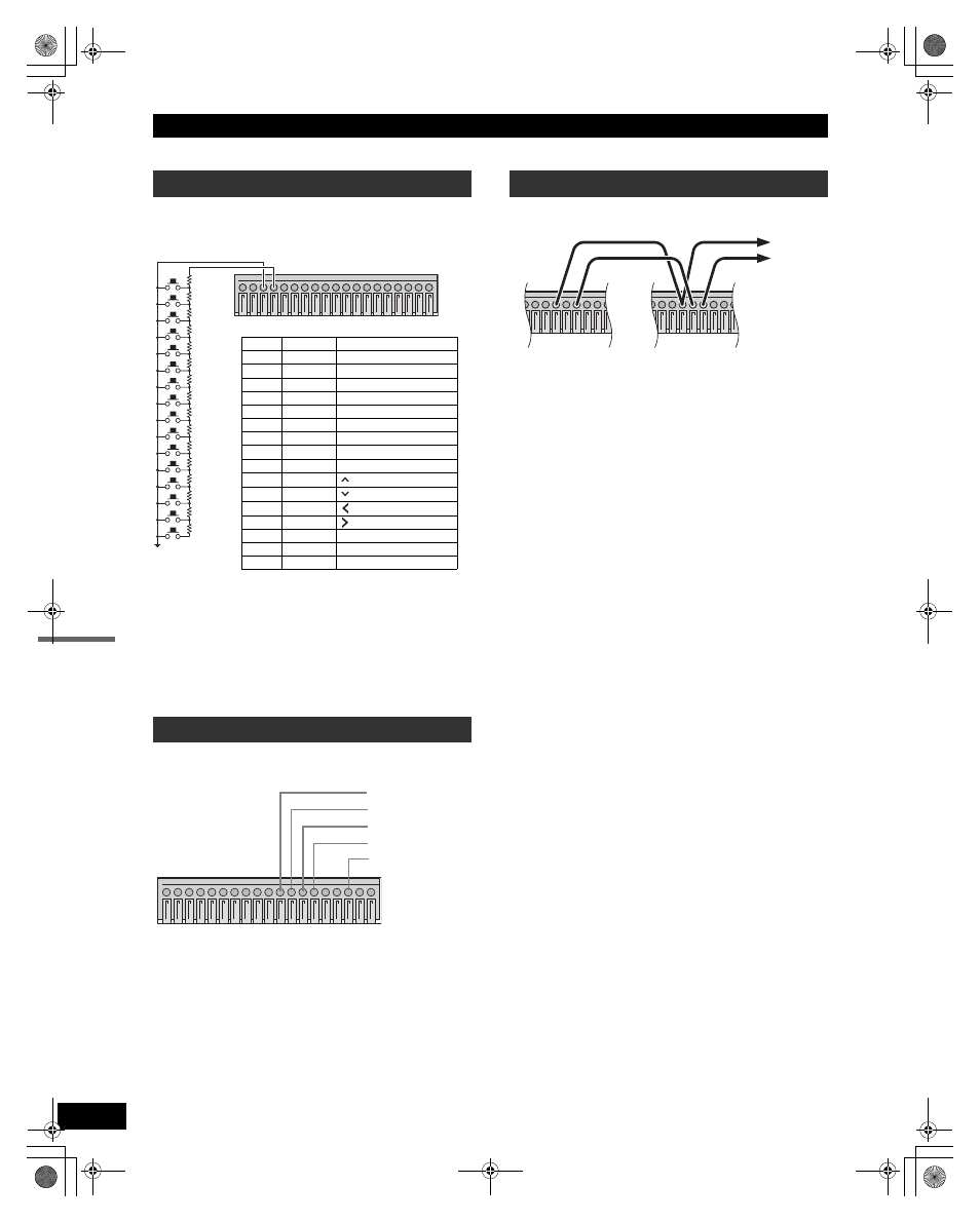
Connect the control terminals by cables as shown below.
Terminal No.
8: COMMON
9: SERIES REC IN
10: NON REC OUT/SERIES REC OUT
Remote control connections
Alarm sensor connections
1 2 3 4 5 6 7 8 9 10 11 12 13 14 15 16 17 18 19
220
220
300
360
470
680
820
1.2k
1.8k
2.2k
3.3k
4.7k
7.5k
13k
27k
68k
SW 1
SW 2
SW 3
SW 4
SW 5
SW 6
SW 7
SW 8
SW 9
SW 10
SW 11
SW 12
SW 13
SW 14
SW 15
SW 16
Key
Resistance
Corresponding button
SW1
220
Ω
CHANNEL button 1
SW2
440
Ω
CHANNEL button 2
SW3
740
Ω
CHANNEL button 3
SW4
1100
Ω
CHANNEL button 4
SW5
1570
Ω
QUAD/SEQUENCE
SW6
2250
Ω
AUDIO
SW7
3070
Ω
SEARCH
SW8
4270
Ω
MENU
SW9
6070
Ω
EXIT/OSD
SW10
8270
Ω
SW11
11570
Ω
SW12
16270
Ω
(REVIEW)
SW13
23770
Ω
(CUE)
SW14
36770
Ω
STILL
SW15
63770
Ω
PLAY/STOP
SW16
70570
Ω
REC/STOP
1 2 3 4 5 6 7 8 9 10 11 12 13 14 15 16 17 18 19
To sensor 1
To sensor 2
To sensor 3
To sensor 4
C (ground) terminal
Series recording connections
5 6 7 8 9 10 11 12 13
5 6 7 8 9 10 11 12 13
2nd DVR
1st DVR
To 3rd
DVR
e00_VDH_M814.book Page 67 Thursday, October 28, 2004 9:59 AM