8 control – Honeywell UDC2500 User Manual
Page 223
Modbus Read, Write and Override Parameters plus Exception Codes
4/07
UDC2500 Universal Digital Controller Product Manual
209
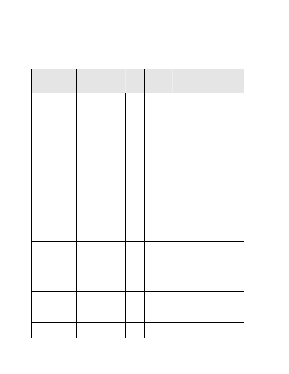
10.7.8 Control
Table 10-16 lists all the register addresses and ranges or selections for the function
prompts in Set-up Group Control.
Table 10-16 Set-up Group – Control
Parameter
Description
Register
Address
Data
Type
Access
Data Range or
Enumerated Selection
Hex
Decimal
Tuning
Parameter
Selection
00AC
172
INT
R/W
0 = One set only
1 = 2 sets keyboard selected
2 = 2 sets with PV automatic
switchover
3 = 2 sets with setpoint (SP)
automatic switchover
Automatic
Switchover
Value (used with
172 selection 2
or 3)
0038
056
FP
R/W
Within the PV Range in
engineering units
Local Setpoint
Source (Number
of LSPs)
00AD
173
INT
R/W
0 = One Local Setpoint
1 = Two Local Setpoints
Power Up Mode
Recall
0082 130
INT R/W Control Setpoint
Mode Mode
0 = MAN
LSP
1 = AUTO
LSP
2 = AUTO
Last RSP
3 = LAST
Last SP
4 = LAST
Last Local SP
RSP Source
0083
131
INT
R/W
0 = None
1 = Input 2
Setpoint
Tracking
008A
138
INT
R/W
0 = None
1 = LSP = PV (when in
Manual)
2 = LSP = RSP (when
switched)
Control Setpoint
High Limit
0007
007
FP
R/W
0 to 100% of PV
(engineering units)
Control Setpoint
Low Limit
0008
008
FP
R/W
0 to 100% of PV
(engineering units)
Control Output
Direction
0087
135
INT
R/W
0 = Direct
1 = Reverse