3 switch rear panel, 2 install the switch, 1 desktop installation – PLANET WGSW-5242 User Manual
Page 28
User’s Manual of WGSW-5242
28
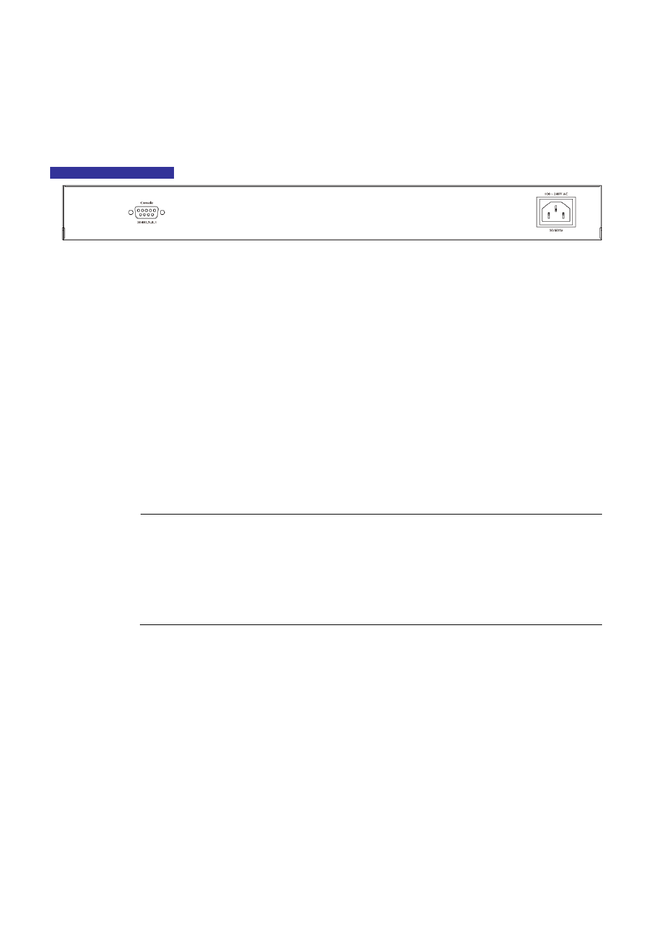
2.1.3 Switch Rear Panel
The rear panel of the Managed Switch indicates an AC inlet power socket, which accept input power from 100 to 240V AC,
50-60Hz.
Figure 2-3
shows the rear panel of these Managed Switch.
WGSW-5242 Rear Panel
Figure 2-3
Rear panel of WGSW-5242
■ Console Port
The console port is a DB9, RS-232 male seria port connector. It is an interface for connecting a terminal directly. Through
the console port, it provides rich diagnostic information includes IP Address setting, factory reset, port management, link
status and system setting. Users can use the attached RS-232 cable in the package and connect to the console port on the
device. After the connection, users an run any terminal emulation program (Hyper Terminal, ProComm Plus, Telix, Winterm
and so on) to enter the statup screen of the device.
■ AC Power Receptacle
For compatibility with electric service in most areas of the world, the Managed Switch’s power supply automatically adjusts
to line power in the range 100-240VAC and 50/60 Hz.
Plug the female end of the power cord firmly into the receptalbe on the rear panel of the Managed Switch. Plug the other
end of the power cord into an electric service outlet then the power will be ready.
Power Notice:
The device is a power-required device, it means, it will not work till it is powered. If your networks should
active all the time, please consider using UPS (Uninterrupted Power Supply) for your device. It will
prevent you from network data loss or network downtime.
In some area, installing a surge suppression device may also help to protect your Managed Switch from
being damaged by unregulated surge or current to the Switch or the power adapter.
2.2 Install the Switch
This section describes how to install your Managed Switch and make connections to the Managed Switch. Please read the
following topics and perform the procedures in the order being presented. To install your Managed Switch on a desktop or shelf,
simply complete the following steps.
2.2.1 Desktop Installation
To install the Managed Switch on desktop or shelf, please follows these steps:
Step1:
Attach the rubber feet to the recessed areas on the bottom of the Managed Switch.
Step2:
Place the Managed Switch on the desktop or the shelf near an AC power source, as shown in
Figure 2-4
.