Preliminar y – Extron Electronics MLC 104 Plus Series User Manual
Page 33
2-17
MLC 104 Plus Series • Operation, Features, and Cabling
PRELIMINAR
Y
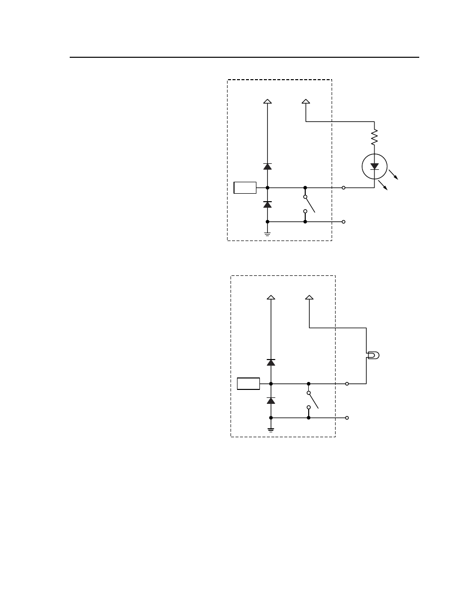
MLC104 DigOutput-03
MLC 104 Plus Series
+12 V
+12 V
2k
Ohms
LED
Digital
Output
GND
CTL
SW 1
Pin 1, 2,
or 3
The digital
output pin
drives an LED
using the
+12 VDC
output of the
controller as a
voltage source.
The LED lights
only when the
I/O pin is set
to “on”
(switch 1 is
closed).
N The I/O pin is capable of sinking a maximum of 250 mA from 12 VDC, max.
MLC104 DigOutput-04
Lamp
MLC 104 Plus Series
+12 V
+12 V
Digital
Output
+12 V Out
GND
CTL
SW 1
The digital
output pin
drives an
incandescent
lamp using the
+12 VDC
output of the
controller as
the voltage
source.
The lamp lights
only when the
I/O pin is set
to “on”
(switch 1 is
closed).
N The I/O pin is capable of sinking a maximum of 250 mA from 12 VDC, max.
d
MLS connector — To control an optional Extron switcher or other RS-232
controllable device, connect a cable between this 3.5 mm direct insertion
captive screw connector and the RS-232 port of the other device. By default
this port supports any Extron switcher without additional drivers. If it is used
to control other products, additional device drivers may be required.
N
The commands issued from this port are standard Extron SIS commands, and
they follow the typical Extron RS‑232 protocol:
• 9600 baud
• 8 data bits
• 1 stop bit
• no parity
If you connect an optional switcher (such as an Extron MLS Series or PVS
Series switcher) to the MLC, you must connect a ground wire between the
switcher and the MLC, as shown in the following diagrams.