Using digital outputs, Preliminar y – Extron Electronics MLC 104 Plus Series User Manual
Page 123
5-19
MLC 104 Plus Series • Special Applications
PRELIMINAR
Y
i
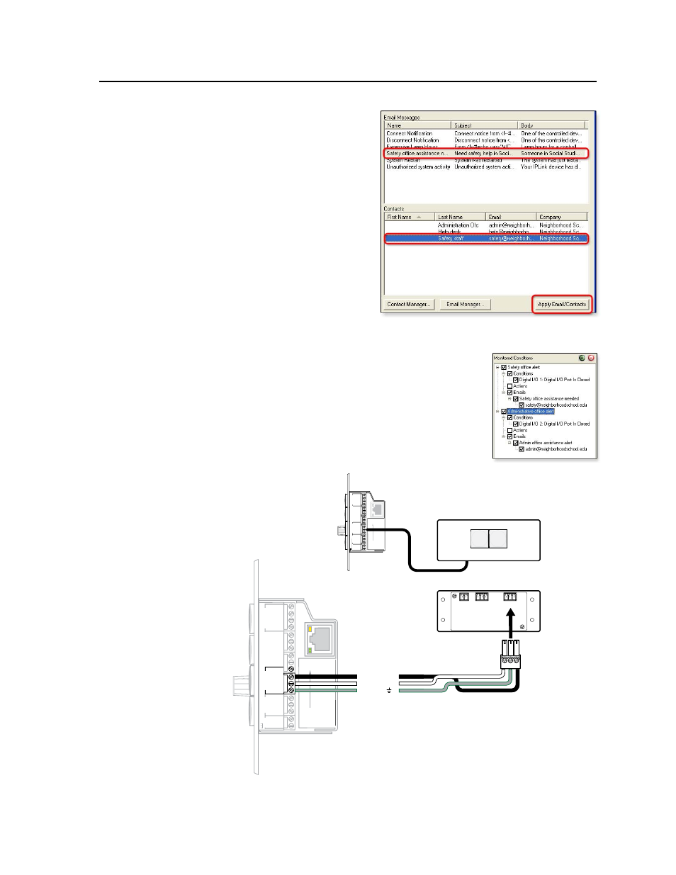
Click on the desired
alert e-mail and on the
name of the contact to
whom the e-mail will
be sent, as shown at
right, then click Apply
Email/Contacts
.
j.
Click Done.
k.
Set up the second
monitored condition by
following steps
2a
-2j but typing in the
second condition’s
name (Administration
office alert
), selecting
Digital I/O 2
as the
device or subject port, and selecting a different e-mail and contact in the
Email Manager.
The monitored conditions are summarized
in the Monitored Conditions area, as shown at
right.
3.
Save the configuration, then build and upload it to
the MLC.
4.
Cable the MLC’s digital input ports to the
appropriate pins of the button panel/switch, as
shown in the following diagram.
2
3
GROUND
1
IR IN
GROUND
IR OUT
CM
SCP
GROUND
GROUND
Tx
Rx
DISPLA
Y
RS-232/IR
LAN
PRESS
TAB
WITH
TWEEKER
TO REMO
VE
A B
MLS
PWR
RS-232 12V
DIGIT
AL
I/O
A B C D E
COMM LINK
+V OUT
GROUND
Tx
Rx
+12V IN
Alert Switch Front View
2
3
GROUND
1
IR IN
GROUND
IR OUT
CM
SCP
GROUND
GROUND
Tx
Rx
DISPLA
Y
RS-232/IR
LAN
PRESS
TAB
WITH
TWEEKER
TO REMO
VE
A B
DIGIT
AL
I/O
A B C D E
COMM LINK
+V OUT
GROUND
Tx
Rx
+12V IN
MLS
RS-232
PWR
12V
MLC’s
Right Side
Ground ( )
Digital input 2
Digital input 1
Connecting an MLC 104 Plus Series
digital input ports to alert buttons
MLC's
digital I/O
ports
PWR
+ G
INPUTS
1 G 2
1 G 2
OUTPUTS
SAFETY ADMIN