Preliminar y – Extron Electronics MLC 104 Plus Series User Manual
Page 31
2-15
MLC 104 Plus Series • Operation, Features, and Cabling
PRELIMINAR
Y
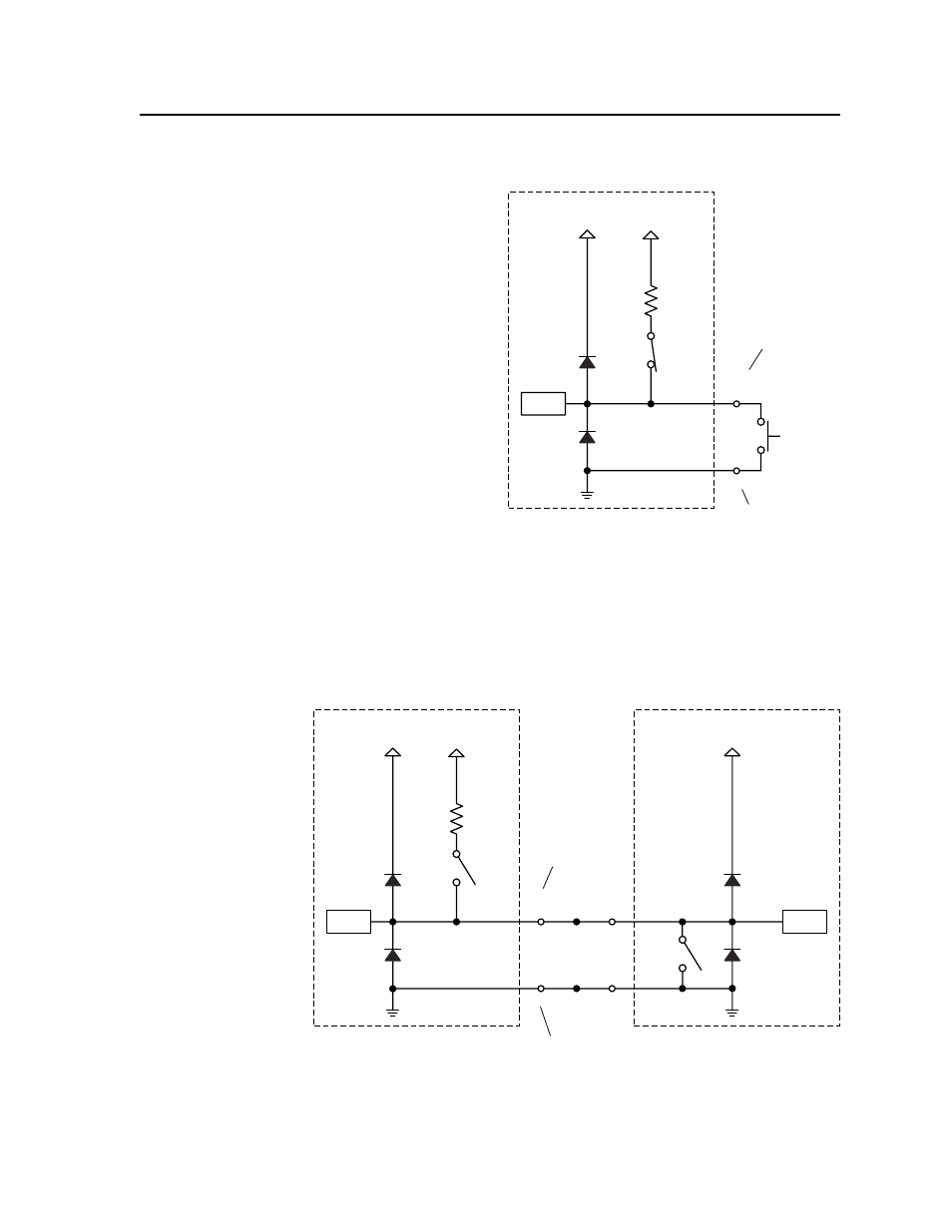
Using these pins and an external switch to trigger digital input
MLC104 DigInput-02
MLC 104 IP Plus
+12 V
Digital
Input
Normally
Open
Switch
GND
2k ohms
SW 2
+5.0 V
CTL
Digital input is triggered
by an external switch
wired between the I/O pin
and ground. The pull-up
resistor to +5.0 VDC is
activated (switch 2 is
enabled/closed).
Pin 1, 2, or 3 of the
Digital I/O Port
Digital I/O Port GND
Using a motorized surface access enclosure to trigger digital input
MLC104 DigInput-04
SW 1
MLC 104 IP Plus
HSA 822M/MS
+12 V
+12 V
Digital
Input
GND
Status
Pin
GND
2k ohms
SW 2
+5.0 V
CTL
CTL
Digital input at the MLC is triggered by a digital output from a motorized Extron
HSA 822M.
A closure to ground (switch 1) occurs when a certain condition is met on the HSA.
This closure to ground triggers the MLC.
The MLC must have the pull-up resistor to +5.0 VDC activated (switch 2 is
enabled/closed).
Pin 1, 2, or 3
of the Digital
I/O Port
Digital I/O Port
GND
See “Using Digital Inputs” in chapter 5, “Special Applications”, for a wiring
diagram for this example.