Preliminar y, Programming and control, cont’d, Command ascii command – Extron Electronics MLC 104 Plus Series User Manual
Page 100: Response, Values
SIS
™
Programming and Control, cont’d
MLC 104 Plus Series • SIS Programming and Control
4-36
PRELIMINAR
Y
Command/response table for special function SIS commands, continued
Command
ASCII
Command
(host to MLC)
Response
(MLC to host)
X?
values
and additional descriptions
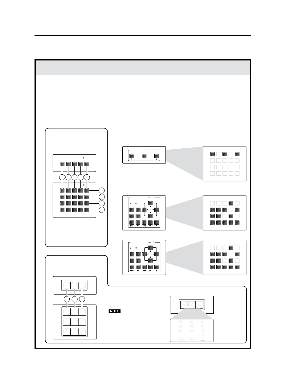
Each control module (IRCM, ACM, RCM, CM) has 20 memory blocks reserved for it, no matter how many buttons are
physically present on the module:
• module 1: blocks 26-45
• module 2: blocks 46-65
• module 3: blocks 66-85
• module 4: blocks 86-105
N
MLC 104 Plus Series units can be connected to a maximum of four control modules.
instructions.
Memory block numbers for each module are sequential from left to right, top row to bottom row, as shown below.
SCREEN POSITION
DOWN
UP
STOP
DVD & VCR CONTROL
PLAY NEXT/FWD PAUSE
STOP
TUNER
Tx
PREV/REW
ENTER
TITLE
MENU
TV/VCR
DVD
VCR
DVD & VCR CONTROL
PLAY NEXT/FWD PAUSE
STOP
TUNER
Tx
PREV/REW
ENTER
TITLE
MENU
TV/VCR
DVD
VCR
CM-3BLB
CM-3BLB
CM-9BLB
CM-3BLB, DIP switch set for address 3 (module 4)
Button/Switch Memory Block Numbering for Control Modules (IRCMs, ACMs, RCMs, CMs)
Memory Block Numbering
for Any Control Module
with Black Buttons
(Example is for Control Module 1)
Memory Block Numbering
for Control Modules with
Clear, Backlit Buttons
26 27 28 29 30
26 27 28
35
30
40
45
31
35
34
33
32
36
40
39
38
37
41
45
44
43
42
26 27 28
86 87 88
26 27 28
29 30 31
32 33 34
Memory Block Numbering Examples
for Modules with Black Buttons
DVD Half (module 1)
IRCM-DV+ with DIP switch set for addresses 0 and 1 (modules 1 and 2)
RCM-SC with DIP switch set for address 2 (module 3)
VCR Half (module 2)
31
35
33
32
36
39
29
37
41
45
44
43
42
66
66
68
70
71
76 77 78 79
67
69
82 83 84
80
81
85
72 73 74 75
26
28
30
31
36 37
38
39
27
29
42 43 44
40
41
45
32 33
34
35
70
68
51
55
53
52
56
59
49
57
61
65
64
63
62
Module 3 has
memory blocks 66-85.
Module 1 has
memory blocks 26-45.
46
48
50
51
56 57
58
59
47
49
62 63 64
60
61
65
52 53
54
55
Module 2 has
memory blocks 46-65.
Module 4
has memory
blocks
86-105.
Buttons and memory blocks are
numbered in a grid of 5 columns
and 4 rows of buttons on each
module, as on the CM-20BB,
shown above.
Backlit button modules feature a grid
of 3 columns and 1 or 3 rows of
buttons, as shown at left.
N
There are still 20 memory
blocks for each module.
•
Module 1: memory blocks 26-45.
•
Module 2: memory blocks 46-65.
•
Module 3: memory blocks 66-85.
•
Module 4: memory blocks 86-105.
CM-3BLB
CM-9BLB
86
87
88
89
90
91
92
93
94
•
•
•
•
•
•
•
•
•
104
105
—