Configuring an auxiliary (mls, pvs) switcher, Setting up passwords for ip models, Printing a wiring block diagram – Extron Electronics MLC 104 Plus Series User Manual
Page 54: Preliminar y, Software-based configuration and control, cont’d
Software-based Configuration and Control, cont’d
MLC 104 Plus Series • Software-based Configuration and Control
3-14
PRELIMINAR
Y
Configuring an auxiliary (MLS, PVS) switcher
An Extron MediaLink Switcher (MLS) or PoleVault Switcher (PVS) can be
connected to the MLC to expand the number of inputs available to the projector/
display. However, if the MLS or PVS switcher is disabled, the MLS RS-232 port
can be used as an auxiliary, bidirectional RS-232 port, just like the Display port. To
enable and configure an auxiliary switcher, follow the Global Configurator Help file’s
procedure to add and configure a MediaLink switcher.
Setting up passwords for IP models
To control access to the MLC through a LAN connection, you can set administrator
and user passwords. Full instructions are available in the MLC 104 Plus Series Setup
Guide
or the Global Configurator Help file’s section on advanced configuration.
1.
Open an existing Extron Global Configurator (GC) project or start a new
project.
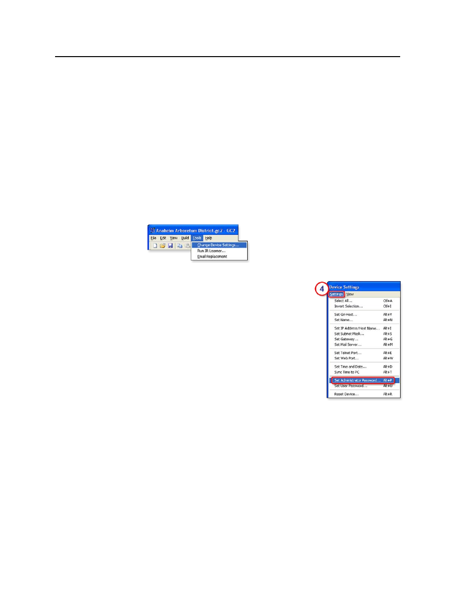
2.
Click Tools and select Change Device Settings from the drop-down menu.
3.
In the Device Settings window, select (click on) the name of the desired MLC.
4.
Click Settings and choose Set Administrator
Password
or Set User Password from the drop-
down menu, as shown at right. A Set for <IP
address
> window appears.
5.
Type the desired password into both areas of
the window and click OK. The Set for... window
closes.
N
Passwords must contain 4 to 12 alphanumeric
characters. Symbols and spaces are not allowed,
and the passwords are case sensitive.
6.
Click the Close button.
7.
Complete the rest of the configuration, save the
project, and upload (build) the configuration to
the MLC. The Upload Manager window appears.
8.
Click Exit after the files have been uploaded.
Printing a wiring block diagram
Once you have configured a system using Global Configurator, you can generate
and print a simple block diagram of what products to wire to which of the MLC’s
ports. The diagram includes model names, DIP switch settings for control modules,
and the type of communication (IR or RS-232) configured for each port. Read the
Global Configurator Help
file’s “Reference Information” section about the File menu
for details.
N
This procedure requires Microsoft Word software. The installer or user must
provide that software. It is not an Extron product.
Procedure overview:
In Global Configurator, click on the File drop-down menu and select Print and
then Wiring Diagram. In the Print Wiring Diagrams window, select the devices
to include in the diagram. Click the Print button at the bottom of the window.