Pinout guide, Preliminar y, Mlc 104 plus series right side panel – Extron Electronics MLC 104 Plus Series User Manual
Page 39
2-23
MLC 104 Plus Series • Operation, Features, and Cabling
PRELIMINAR
Y
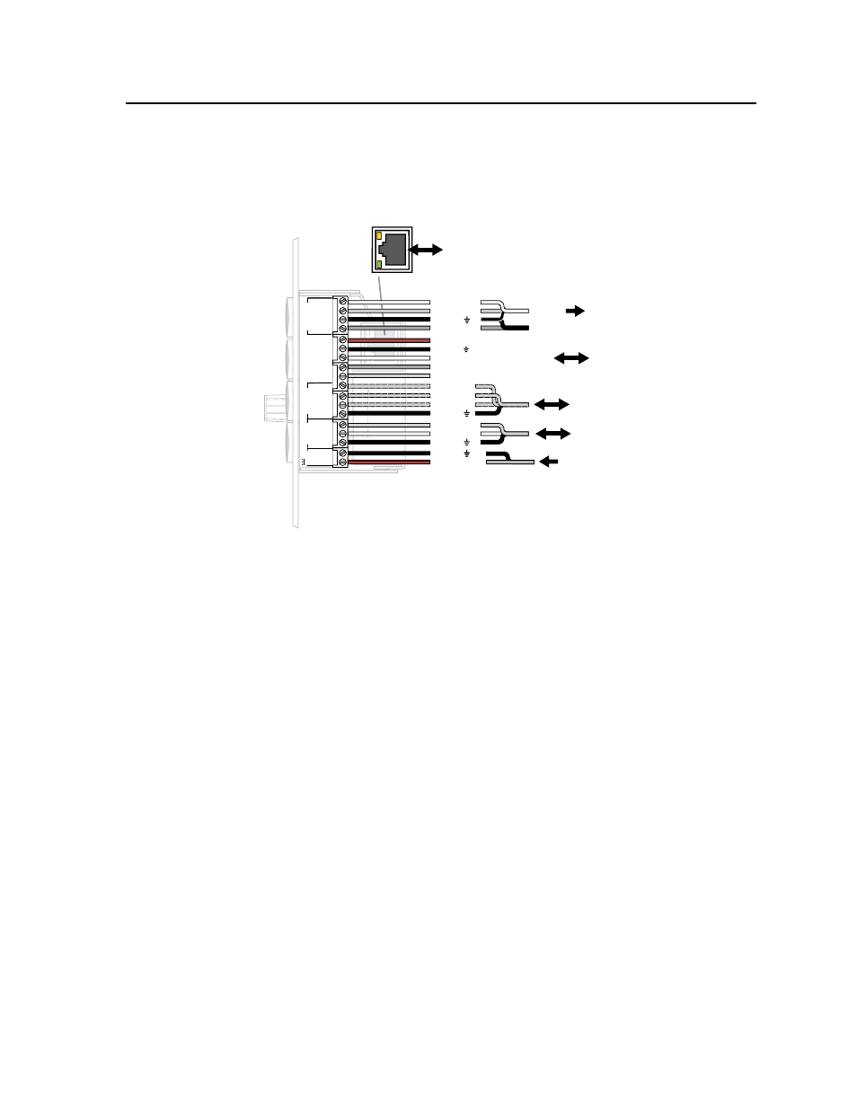
Pinout Guide
The illustration below summarizes the pin assignments of all of the MLC’s side
panel connectors that are covered in detail on the preceding pages.
2
3
GROUND
1
IR IN
GROUND
IR OUT
CM
SCP
GROUND
GROUND
Tx
Rx
DISPLA
Y
RS-232/IR
LAN
PRESS
TAB
WITH
TWEEKER
TO REMO
VE
A
B
MLS
PWR
RS-232 12V
DIGIT
AL
I/O
A B C D E
COMM LINK
+V OUT
GROUND
Tx
Rx
+12V IN
LAN
LAN
PRE
SS
TAB
WIT
H
TWEEKER
TO
REM
O
VE
MLC 104 Plus Series
Right Side Panel
To / from sensors, switches,
control equipment (screen controllers,
lights, relays), LEDs,
etcetera
Ground ( )
Transmit (Tx)
Receive (Rx)
To/from an optional Extron switcher
From an external 12 VDC, 2 A (max.)
power supply
Ground ( )
Receive (Rx)
Transmit (Tx)
To a projector or display
(or source device)
RS-232
IR
IR Output
Ground ( )
Digital I/O
Digital I/O
Digital I/O
Ground ( )
+12 VDC input
SCP communication (IR)
Modulated IR (for IR Link or IRL 20)
Ground ( )
IRCM, ACM, RCM
+12 VDC
To / from optional Extron
control modules, IR Link IR
repeater, or SCP control pads
To / from LAN
or Internet
(IP models only)