Power connection, Top panel: ir learning sensor, Power connection -20 – Extron Electronics MLC 104 Plus Series User Manual
Page 36: Top panel: ir learning sensor -20, Preliminar y, Operation, features, and cabling, cont’d
Operation, Features, and Cabling, cont’d
MLC 104 Plus Series • Operation, Features, and Cabling
2-20
PRELIMINAR
Y
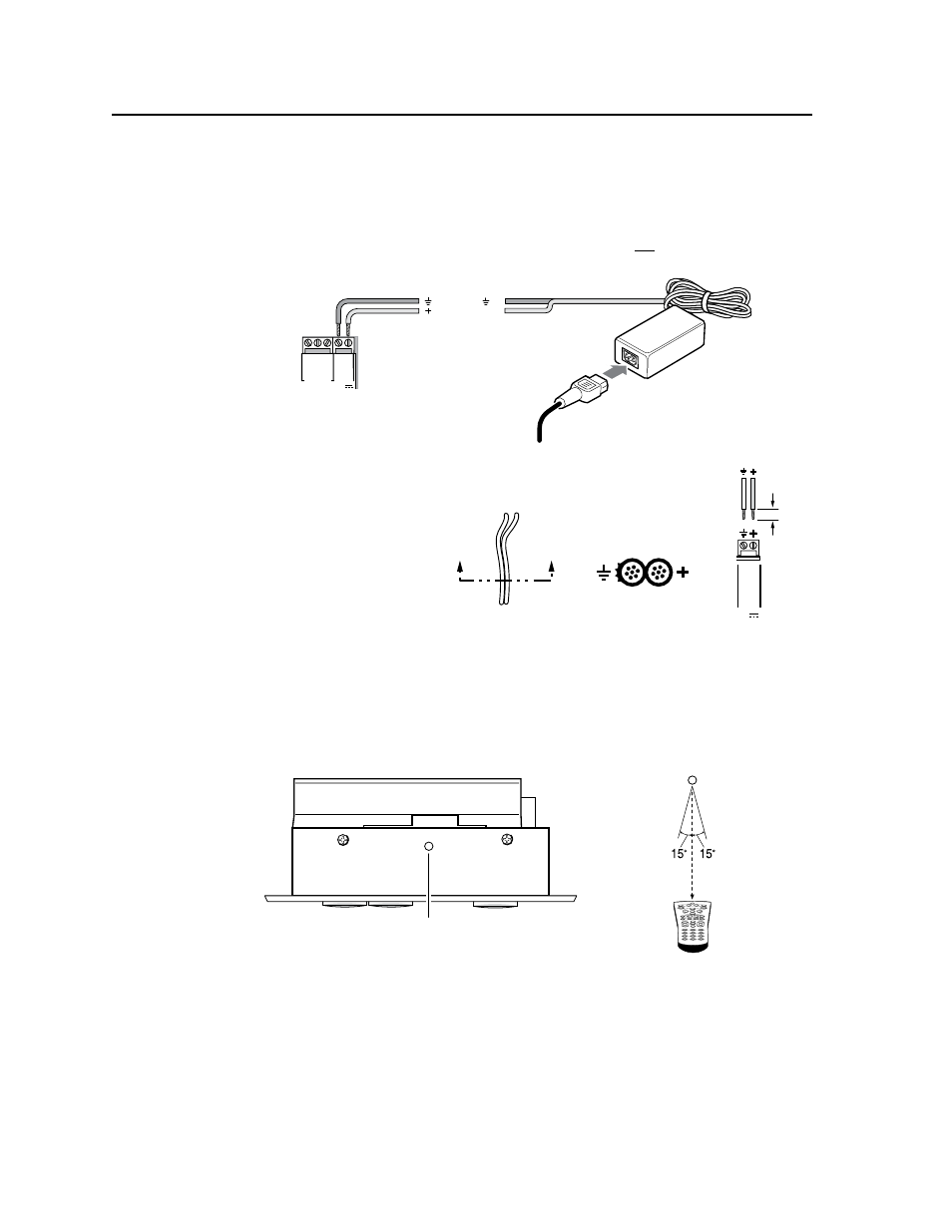
Power connection
e
PWR (power) connector — To provide power to the MLC, connect a cable
between this port and a 12 VDC, 2 amp (maximum) power supply. See the
following diagram.
N
Power the controller via an external power supply, not from an Extron switcher.
The controller requires a separate 12 VDC power supply.
Connecting an
MLC 104 Plus Series controller
to an external power supply
MLC/IR
A B C
MLS 304SA Rear Panel
Connecting an MLC 104 Plus Series
to a MediaLink Switcher and an external power supply
MediaLink
Switcher's
rear panel
MLC/IR port
NOTE
You must connect a
ground wire between
the MLC and MLS.
MLC's
MLS and
Power
ports
MLC's
MLS and
Power
ports
NOTE
If you use cable that
has a drain wire, tie
the drain wire to
ground at both ends.
2
3
G
R
O
U
N
D
1
IR
IN
G
R
O
U
N
D
IR
O
U
T
C
M
SC
P
GR
OU
ND
GR
OU
ND
Tx
R
x
DISPLAY
RS-232/IR
LAN
PRESS TAB WITH
TWEEKER TO REMOVE
A B
DIGITAL
I/O
A B C D E
COMM LINK
+V
O
U
T
G
R
O
U
N
D
Tx
R
x
+1
2V
IN
MLS
RS-232
PWR
12V
AUDIO INPUTS
LINE LEVEL
MONO
AUDIO
AUDIO
AUX/MIX
ADJUST
-42dB
TO
+24dB
L
R
L
R
1
2
INPUTS
OUTPUTS
VIDEO
H
V
B
G
R
1
2
INPUTS
3
4
MONITOR OUT
LINEOUT
100-240V
1.0A MAX.
50-60Hz
RS-232/MLC/IR
Tx Rx IR
12V
A B C
PREAMP
L
R
L
R
AMPLIFIED OUTPUT
4/8 ohm
RIGHT
LEFT
STEREO OR DUAL MONO
C
LA
S
S
2
W
IR
IN
G
MLC 104 IP Plus
Right Side Panel
PWR
12V
MLS
RS-232
GR
OU
ND
GR
OU
ND
A B
Tx
R
x
+1
2V
IN
PWR
12V
MLS
RS-232
GR
OU
ND
GR
OU
ND
A B
Tx
R
x
+1
2V
IN
Ground ( )
Transmit (Tx)
B Receive (Rx)
A
Transmit (Tx)
Receive (Rx)
B
A
Strip wires 3/16” (5 mm) max.
Ground ( )
+12 VDC input
Ground ( )
+12 VDC input
Ground all devices.
External
Power Supply
(12 VDC)
External
Power Supply
(12 VDC)
External
Power Supply
Ground all devices.
N
Check the power supply’s
polarity before
connecting it
to the MLC.
See the
illustration at
right.
Top panel: IR learning sensor
In most cases, Extron has already produced an IR driver file for controlling the
projector or display you plan to use. If a device driver file is not available, you can
create your own using Extron IR Learner software, the projector or display’s remote
control, and the MLC’s IR learning receiver sensor, shown below.
IR
MLC 104 Plus Series
Top Panel
IR Learning
Receiver
IR
1
2
3
4
5
6
7
8
0
9
2–12"
(4–30 cm)
Refer to the IR Learner Help File for instructions on how to create the driver file.
During the IR command capturing process, hold the projector’s remote between 2"
and 12" from and pointed directly at the MLC’s IR learning sensor, as shown above.
N
The MLC 104 Plus requires IR Learner version 1.23 or higher.
3/16”
(5 mm)
MAX.
MLC's
Power
Port
12V
PWR
GR
OUND
+12V IN
Power Supply Output Cord
End View of Power
Supply Output Cord
A
A
SECTION A–A