Preliminar y – Extron Electronics MLC 104 Plus Series User Manual
Page 35
2-19
MLC 104 Plus Series • Operation, Features, and Cabling
PRELIMINAR
Y
f
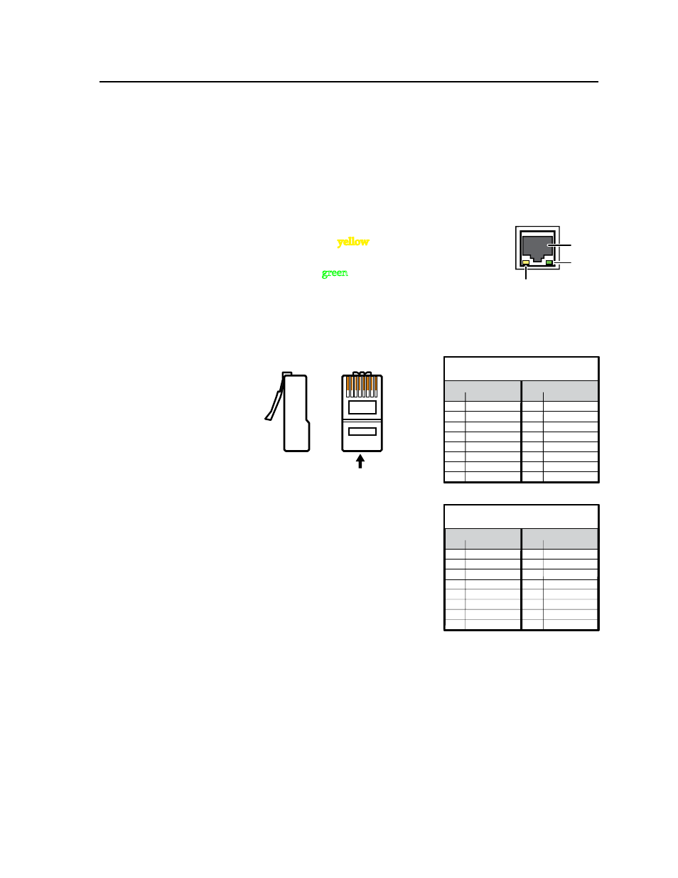
LAN (IP) connector and LEDs (IP models only) — An Ethernet connection
can be used to connect and to control the MLC (and the devices connected to
it) in an Ethernet network. Plug a cable into this RJ-45 socket and connect the
other end of the cable to a network switch, hub, router, or PC connected to an
Ethernet LAN or the Internet.
• For 10Base-T (10 Mbps) networks, use a CAT 3 or better cable.
• For 100 Base-T (max. 155 Mbps) networks, use a CAT 5 cable.
You will also need to configure this port before using it.
Activity LED
— This yellow LED blinks to indicate
network activity.
Link LED —
This green LED lights to indicate a good
network connection.
• Use a straight-through cable for connection to a switch, hub, or router.
• Use a crossover cable for connection directly to a PC. Wire the connector
as shown in the following tables.
Configure the settings for this
port via either SIS commands
or Global Configurator. See the
programming sections of this
manual (chapters 3 and 4) for
details.
LAN port defaults:
• MLC’s IP address: 192.168.254.254
• gateway’s IP address: 0.0.0.0
• subnet mask: 255.255.0.0
• DHCP: off
LAN
RJ-45
Port
Link
LED
Activity
LED
12345678
RJ-45 Connector
Insert
Twisted
Pair Wires
Pins:
Side View
Straight-through Cable
(for connection to a switch, hub, or router)
End 1
End 2
Pin Wire Color
Pin
Wire Color
1
white-orange
1
white-orange
2
orange
2
orange
3
white-green
3
white-green
4
blue
4
blue
5
white-blue
5
white-blue
6
green
6
green
7
white-brown
7
white-brown
8
brown
8
brown
Crossover Cable
(for direct connection to a PC)
End 1
End 2
Pin Wire Color
Pin Wire Color
1
white-orange
1
white-green
2
orange
2
green
3
white-green
3
white-orange
4
blue
4
blue
5
white-blue
5
white-blue
6
green
6
orange
7
white-brown
7
white-brown
8
brown
8
brown