Preliminar y, Operation, features, and cabling, cont’d – Extron Electronics MLC 104 Plus Series User Manual
Page 32
Operation, Features, and Cabling, cont’d
MLC 104 Plus Series • Operation, Features, and Cabling
2-16
PRELIMINAR
Y
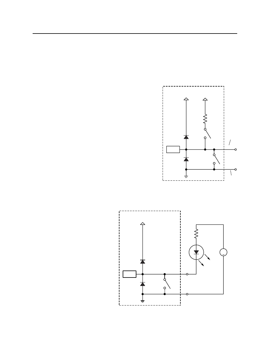
Digital output
— To power LEDs, incandescent lights, or other devices that
accept a TTL signal, or to provide contact closure control for projector lifts,
motorized screens, room or light switches via an Extron IPA T RLY4, you can
use one or more of these ports as a digital output. Each I/O port is capable of
accepting 250 mA, maximum. If the application calls for TTL compatibility,
the digital output circuit can be set up to provide a 2k ohm pull-up resistor to
+5 VDC.
MLC104 DigOutput-01
MLC 104 Plus Series
+12 V
SW 1
I/O
GND
2k ohms
SW 2
+5.0 V
CTL
When a digital I/O pin is configured
as a digital output, it is set to offer
two output states: “on” and “off”.
When the port is set to an “on” state,
switch 1 (SW 1) closes and the I/O
pin connects to ground.
When the port is set to the “off” state,
switch 1 opens and the I/O pin floats.
The MLC 104 Plus Series controller
cannot provide TTL level outputs
like some of the IP Link interfaces.
Switch 2 cannot be enabled when
I/O pin is used as an output.
When used as a digital output, a
digital output pin on the MLC may
not work with certain devices
requiring contact closure control.
Although the illustration shows a
short to ground when switch 1 is
enabled, the actual circuit does not
provide a completely grounded output. For any devices requiring contact closure
control, it is recommended that relays be used.
Pin 1,
2, or 3
of the
Digital
I/O Port
Digital
I/O
Port
GND
MLC104 DigOutput-02
+
MLC 104 Plus Series
+12 V
390
Ohms
LED
+5 V
External
Source
Digital
Output
GND
CTL
The digital
output pin
drives an LED
using an
external
+5 VDC source.
The LED lights
only when the
I/O pin is set
to “on”
(switch 1 is
closed).
SW 1
N The I/O pin is capable of sinking a maximum of 250 mA from 12 VDC, max.