Preliminar y, Operation, features, and cabling, cont’d, 1on 2 3 4 – Extron Electronics MLC 104 Plus Series User Manual
Page 30
Operation, Features, and Cabling, cont’d
MLC 104 Plus Series • Operation, Features, and Cabling
2-14
PRELIMINAR
Y
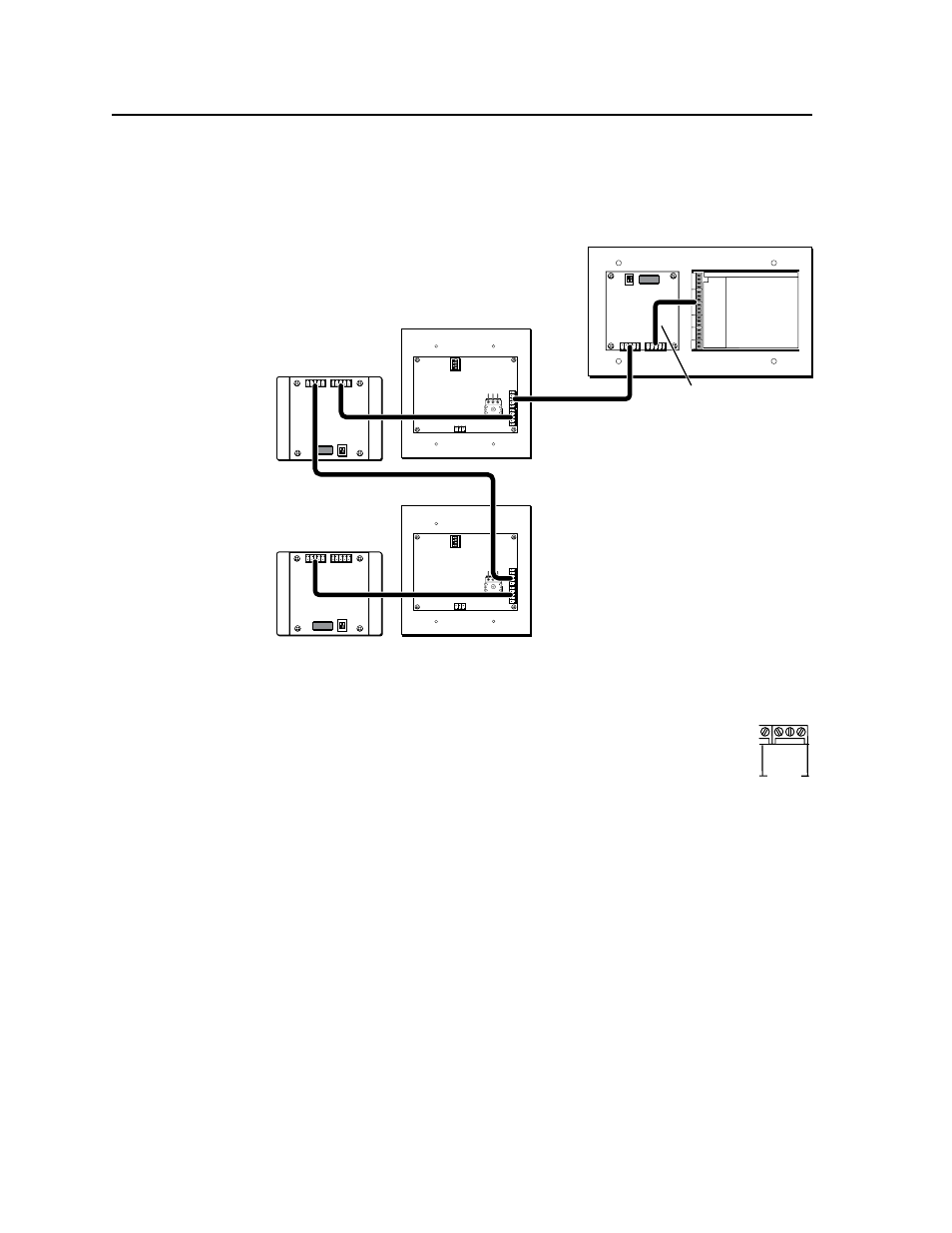
MLC 104 IP Plus DV+ connections
:
The MLC 104 IP Plus DV+ consists of an MLC 104 IP Plus controller and an
IRCM-DV+ installed in a high-impact plastic faceplate. The wiring is the same as in
the previous diagram, except the
IRCM-DV+ is cabled to the MLC at the
factory, as shown in the following
diagram.
An MLC 104 IP Plus DV+ with SCPs and additional control modules
c
Digital I/O ports — The Digital I/O area (shown at right) provides
three ports that can be configured as digital inputs or outputs,
with or without +5 VDC pull-up. Connecting these ports to
sensors, switches, LEDs, or relays allows for a way to trigger
events or functions (such as triggering relays, issuing commands,
or sending an e-mail) that have been configured using Global
Configurator (GC) software.
C
Configure these ports using Global Configurator software or SIS commands
first, and then connect wires the MLC’s ports. A mismatch between port
configuration and wiring can cause malfunctions or unit failure.
Digital input
— To allow the MLC to monitor devices such as push buttons,
connect a switch, motion sensor, moisture sensor, tally feedback output, or a
similar item to a digital input port. When one of these ports is configured as
a digital input, it is set to measure two states: high and low. The port accepts
0 to 12 VDC input. The threshold voltages are as follows: a voltage below
2.0 VDC is measured as logic low, and a voltage above 2.8 VDC is measured
as logic high. There is also an internal, +5 VDC, selectable, pull-up resistor for
this circuit.
MLC 104 IP Plus DV+ Rear Panel
A
D
B
C
E
A
D
B
C
E
RUN
100
A
D
B C
E
A
D
B C
E
1
ON
2
3
4
J1
SCP 104 Rear Panel
IRCM-DV+
Rear Panel
A
D
B C
E
A
D
B C
E
1
ON
2
3
4
J1
SCP 104 Rear Panel
IRCM-DV+
Rear Panel
Factory-wired
MLC - to - IRCM-DV+
Connection
Right
Side Panel
2
3
G
R
O
U
N
D
1
DIGITAL
I/O