Preliminar y, 1on 2 3 4, Mlc 104 plus series rear panel – Extron Electronics MLC 104 Plus Series User Manual
Page 29: Scp 104 rear panel, Cm-3blb rear, Cm-3blb front
2-13
MLC 104 Plus Series • Operation, Features, and Cabling
PRELIMINAR
Y
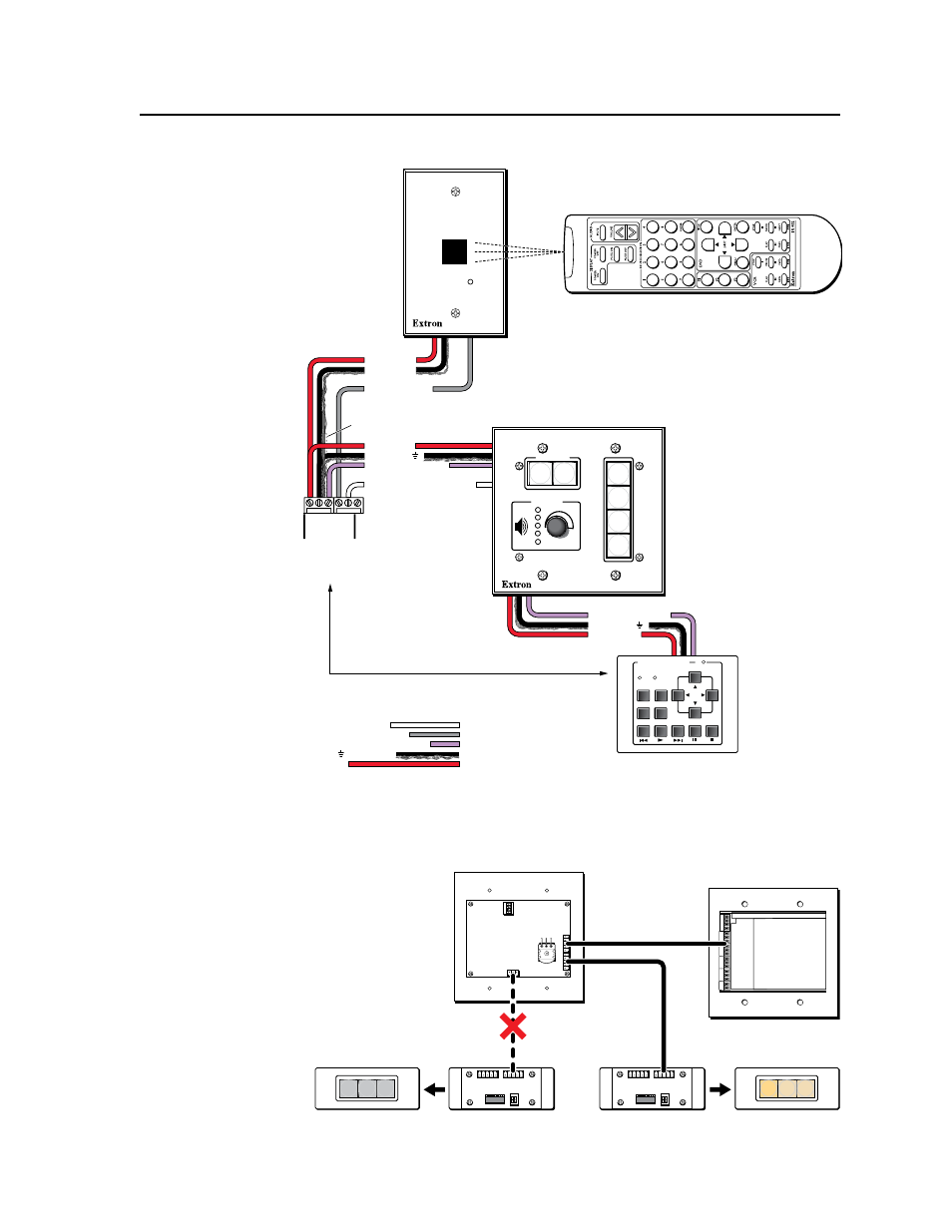
Extron CTLP Cable Color Code:
Ground ( ) & Drain Wire
E
D
C
B
A
SCP Communication
Modulated IR (for IR Link)
Control Module Communication
+12 VDC
= White
= Black and Drain Wire
= Violet
= Gray
= Red
Heat Shrink over Drain Wire
MLC 104 Plus Series
Right Side Panel
1
IR
IN
C
M
SC
P
A B C D E
COMM LINK
+V
O
U
T
G
R
O
U
N
D
D
B
A
E
D
C
B
A
SCP communication (IR)
Modulated IR
(from IR Link)
Ground ( )
IRCM, ACM, RCM
+12 VDC
C
B
A
Maximum =
2 SCPs
Per System
Maximum =
4 Control
Modules
(4 module
addresses)
Maximum =
1 IR Link
Ground ( )
IRCM/ACM/RCM
+12 VDC
Ground
and Drain
+12 VDC
DVD & VCR CONTROL
PLAY NEXT/FWD PAUSE
STOP
TUNER
Tx
PREV/REW
ENTER
TITLE
MENU
TV/VCR
DVD
VCR
IRCM-DV+
SCP 104
IR Link
IR 402
SIGNAL
IR LINK
DISPLAY
VOLUME
ON
OFF
VCR
DVD
PC
SCP 104
1
2
3
4
200' (61 m) Max.
to Last Device
Basic connections to an SCP, control module, and IR signal repeater
N
If you connect a CM‑3BLB or CM‑9BLB to an SCP 226’s 3‑pole connector
instead of to
its 5‑pole
connector,
the
CM‑xBLB
control
module’s
buttons will
not light.
MLC 104 Plus Series
Rear Panel
RUN
100
1
ON
2
3
4
J1
SCP 104 Rear Panel
A
D
B C
E
A
D
B C
E
CM-3BLB Rear
A
D
B C
E
A
D
B C
E
CM-3BLB Rear
CM-3BLB
CM-3BLB Front
CM-3BLB
CM-3BLB Front