Preliminar y, Special applications, cont’d – Extron Electronics MLC 104 Plus Series User Manual
Page 130
Special Applications, cont’d
MLC 104 Plus Series • Special Applications
5-26
PRELIMINAR
Y
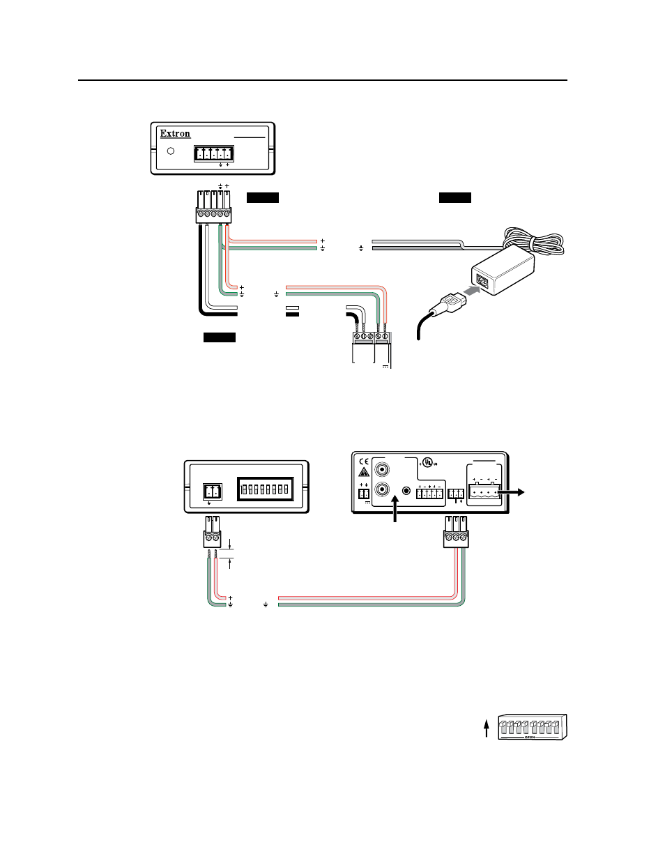
Connecting an MLC 104 Plus Series controller
to an MLA-VC10 and an external power supply
NOTE
You must connect a
ground wire between the
MLC and MLA-VC10.
MLC's MLS and
Power ports
NOTE
If you use cable that has a
drain wire, tie the drain wire
to ground at both ends.
MLA-VC10 Front Panel
MLA-VC10
POWER/
STATUS
A B
MLC/RS-232
POWER
NOTE
The external power supply
provides power to both the
MLA-VC10 and the MLC.
PWR
12V
MLS
RS-232
GR
OU
ND
GR
OU
ND
A B
Tx
R
x
+1
2V
IN
Ground ( )
+12 VDC input
External
Power Supply
(12 VDC)
Ground all devices.
Ground ( )
+12 VDC
Transmit (Tx)
B Receive (Rx)
A
Transmit (Tx)
Receive (Rx)
B
A
A B
MLA-VC10 Rear Panel
MPA 122 Rear Panel
CTRL
1 2 3 4 5 6
ON
7 8
CONFIGURATION
AMP/MIXER
CONTROL
POWER
12V
3A MAX
OUTPUTS
4/8 Ohms
INPUTS
L
R
L
R
REMOTE
10V
VOL/MUTE
L
MPA 122
R
C
US
For the MPA 122 or MPA 181T,
connect the MLA to pins 2 and 3.
Pin 1 = 10 VDC reference
voltage
Pin 2 = variable control voltage
(0 to 10 V) or mute; 0 V
is mute and 10 V
provides max. volume
Pin 3 = GND
Connecting an MLA-VC10 to an MPA122
0 - 10 VDC
5/16” (7 mm) MAX.
Ground ( )
To Speakers
From
Audio
Source
N
For three‑terminal amps, always connect the MLA‑VC10 to the control voltage
terminal and ground terminal of the amp’s control port. Leave the other
terminal (+10V for Extron MPA models) open (not connected).
2.
Set the MLA-VC10’s eight DIP switches to configure the it for the control
voltage required by the amplifier. The Extron MPA 122
and MPA 181T accept up to 10 VDC, so set all of the DIP
switches up (On), as shown at right.
If you use a different amplifier, read the amplifier’s
manual and the MLA-VC10’s manual to determine the voltage the amplifier
requires and how to set the MLA’s DIP switches.
3
4
1
2
7
8
5
6
ON
CONFIGURATION