Using digital outputs, Controlling a low voltage screen motor controller, Cabling the equipment – Extron Electronics MLC 104 Plus Series User Manual
Page 124: Cabling the equipment -20, In chapter, Preliminar y, Special applications, cont’d
Special Applications, cont’d
MLC 104 Plus Series • Special Applications
5-20
PRELIMINAR
Y
5.
Power on the equipment, and test the system. When one button is pressed, it
makes momentary contact, completing the circuit with MLC digital input 1.
The MLC’s monitor detects the change and sends out the safety alert e-mail
to the safety office. When the other button is pressed, it briefly completes the
circuit with digital input 2, triggering the MLC to issue the administration
office e-mail alert.
6.
Make any needed changes and complete the installation.
Using Digital Outputs
To power devices that accept a TTL signal or to provide contact closure control for
projector lifts, motorized screens, room or light switches via an Extron IPA T RLY4,
you can use one or more of the MLC’s digital I/O ports configured for digital
output. When the port is set to an “on” state, (the circuit is closed), the I/O pin is
connected to ground. Each I/O port is capable of accepting 250 mA, maximum.
When the port is set to the “off” state (the circuit is open), the output pin is floating.
If the application calls for TTL compatibility, the digital output circuit can be set up
to provide a 2k ohm pull-up resistor to +5 VDC.
Controlling a Low Voltage Screen Motor Controller
The MLC 104 Plus Series does not have built-in relays that can be connected
directly to a low voltage screen controller. However, with the addition of an Extron
IPA T RLY4 relay controller and a few configuration steps, you can still raise or
lower a projection screen using the MLC, a screen controller, and a screen control
motor.
Follow the procedures in this section to cable the devices and then configure the
MLC for this application.
Cabling the equipment
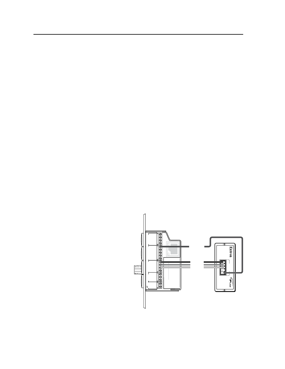
1.
Connect the MLC to an IPA T RLY4 ‘s front panel inputs as shown below.
•
The MLC
provides
12 VDC to the
IPA’s common
voltage pin (C).
•
Each MLC
digital I/O
port (1, 2, 3)
connects
to the
corresponding
relay input
pin (1, 2, 3) on
the IPA.
N
Extron Comm‑Link cable (CTL, part #22‑148‑02/‑03; or CTLP, part
#22‑119‑02/‑03) can be used for these connections.
2.
Connect the IPA T RLY4’s rear panel relay ports to the low voltage screen
controller. The following illustrations provide examples of how to wire
the IPA T RLY4 to typical low voltage screen controllers. However, your
1
2
3
GROUND
+12V OUT
CM
GROUND
IR OUT
GROUND
SCP
GROUND
Tx
Rx
DISPLA
Y
RS-232/IR
A B C D E
COMM LINK
LAN
PRESS
TAB
WITH
TWEEKER
TO REMO
VE
A B
MLS
RS-232
PO
WER
12V
DIGIT
AL
I/O
IR IN
Tx
GROUND
Rx
+12V IN
IP
A
T RL
Y4
1 2 3 4
C
INPUTS
MLC 104 Plus Series
Right Side
IPA T RLY4
Front Panel
Relay 1
Relay 2
Relay 3
+12 VDC