Working with combination source devices, Available methods, Preliminar y – Extron Electronics MLC 104 Plus Series User Manual
Page 111: 7 mlc 104 plus series • special applications
5-7
MLC 104 Plus Series • Special Applications
PRELIMINAR
Y
Working With Combination Source Devices
Many combination DVD-VCR players can output the video signals from both the
video tape and the DVD parts on a single port. If you connect this single output
to one input on a switcher (or projector), the switcher has no way to automatically
know whether it receives input from the DVD or from the VCR; the switcher treats
it as one input device and does not switch between the two.
Available methods
There are several ways to work around the single-input limitation to make both the
DVD and VCR media accessible to the switcher, including the following methods:
• Using separate source output ports on the DVD-VCR player
• Using a distribution amplifier with the switcher
• Using separate IRCM control modules for DVD-VCR control
• Using an IRCM-DV+ control module for DVD-VCR control
Using an IRCM-DV+ control module and one MLC input button
for DVD-VCR control
If the combination DVD-VCR player has only one available output port and neither
a distribution amplifier nor a pair of control modules [(IRCM-DVD or
IRCM-DVD+) and IRCM-VCR] is available for use, you can create a special
configuration to allow control via the MLC 104 Plus Series or
SCP 104 front panel and an optional IRCM-DV+.
An IRCM-DV+ normally must be associated with two
different MLC or projector inputs, one for the DVD half
of the IRCM-DV+, one for the VCR half. However, in this
installation example, both halves will be associated with the
same input.
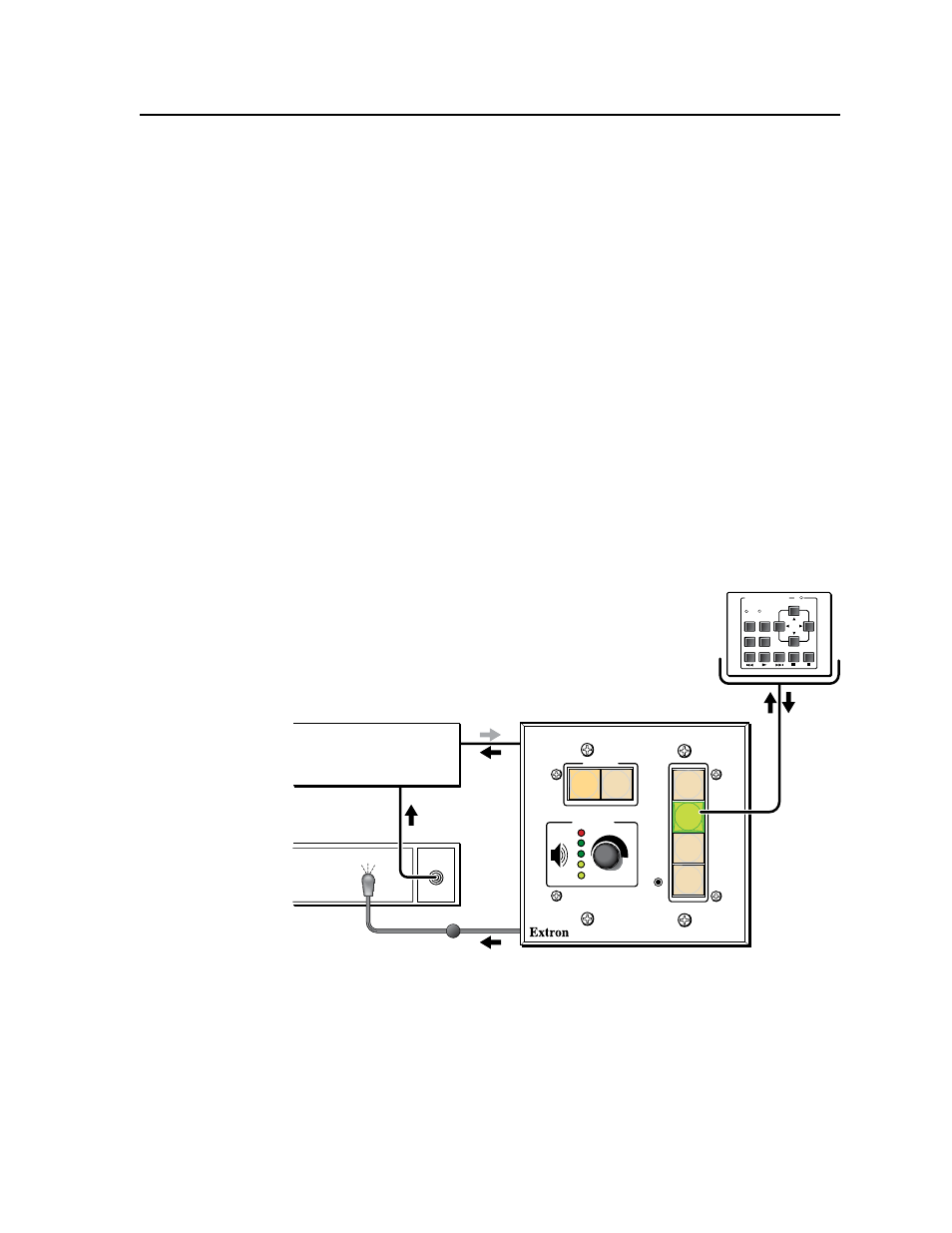
In this example (shown above and described in the following procedure), the
DVD/VCR player’s output is connected to switcher/projector input 2, which is
associated with the MLC 104 Plus Series’s input 2 button.
N
Detailed instructions on basic configuration via software are available in the
MLC 104 Plus Series Setup Guide, the Global Configurator Help file, and
in chapter 3 of this manual.
N
The numbers in the following sample screen images correspond to the
procedure’s step numbers.
OUTPUT
DVD-VCR
Player
Switcher or
Projector
MLC 104 IP Plus
IR Emitter
CONFIG
DISPLAY
VOLUME
MLC 104 IP PLUS
ON
VCR
DVD-
VCR
PC
OFF
1
2
3
4
DVD & VCR CONTROL
PLAY NEXT/FWD PAUSE
STOP
TUNER
Tx
PREV/REW
ENTER
TITLE
MENU
TV/VCR
DVD
VCR
IRCM-DV+