Figure 27 battery connections, Installation drawings 42, Ups module e xt . b a tt – Emerson Liebert NX 480V User Manual
Page 50: Ac 480v field-supplied, Ac 120v (to alber controller), C&d battery enersys
Installation Drawings
42
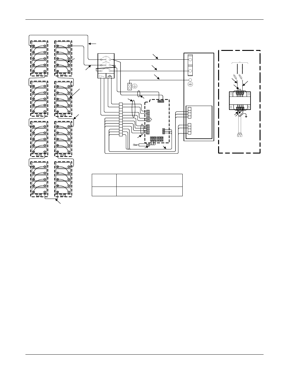
Figure 27 Battery connections
H1
H2
H3
X2
X3
X1
H4
X4
B rown
B lue
Y ellow/Green
AC 480V
Field-Supplied
UPS
Module
E
xt
. B
a
tt.
11
12
14
C1
C2
MX
AUX
+
1
2
3
4
5
6
7
8
9
10
11
12
AC 120V
(To Alber Controller)
Option: Power for Alber System
X 100
X102
+2
20
V
-
1
2
3
X7_J22
W/B lk
WHITE
Red
1
2
3
4
1
2
3
4
U2 PCB
X3_J10
RED
BLK
X108
B CB Control B oard
UHW241C2
X101
RE D
B LA CK
GROUND
NE GA TIV E
P OS ITIV E
Bay #2
Bay #1
32 Pcs
1
9
10
11
12
80 Pcs
3 6 Pcs
3
6
5
7
8
13
100
101
TB 1
W/R
W/ R
W/ B lk
W/ B lk
Y ellow COM
White
White
B lk
B lk
B rn
B rn
Grn
Grn
Wht
Wht
White
White
B lk
B lk
Red
Red
X104
X103
X105
X106
103
108
White
W/ B lk
W /R
White
-
22
21
22
21
NOTE:
1. All service and initial connection of batteries must be
performed by qualified service personnel.
2.Typically used for:
C&D Battery
Enersys
UPS12-100MR,UPS12-150MR,
UPS12-210MR
HX205-FR
B lue NO
102
Temp
530628
Pg. 1, Rev. 0