2 your thinconnect4, Thinconnect4 – EXP Computer ThinConnect4 User Manual
Page 16
<6>
ThinConnect4
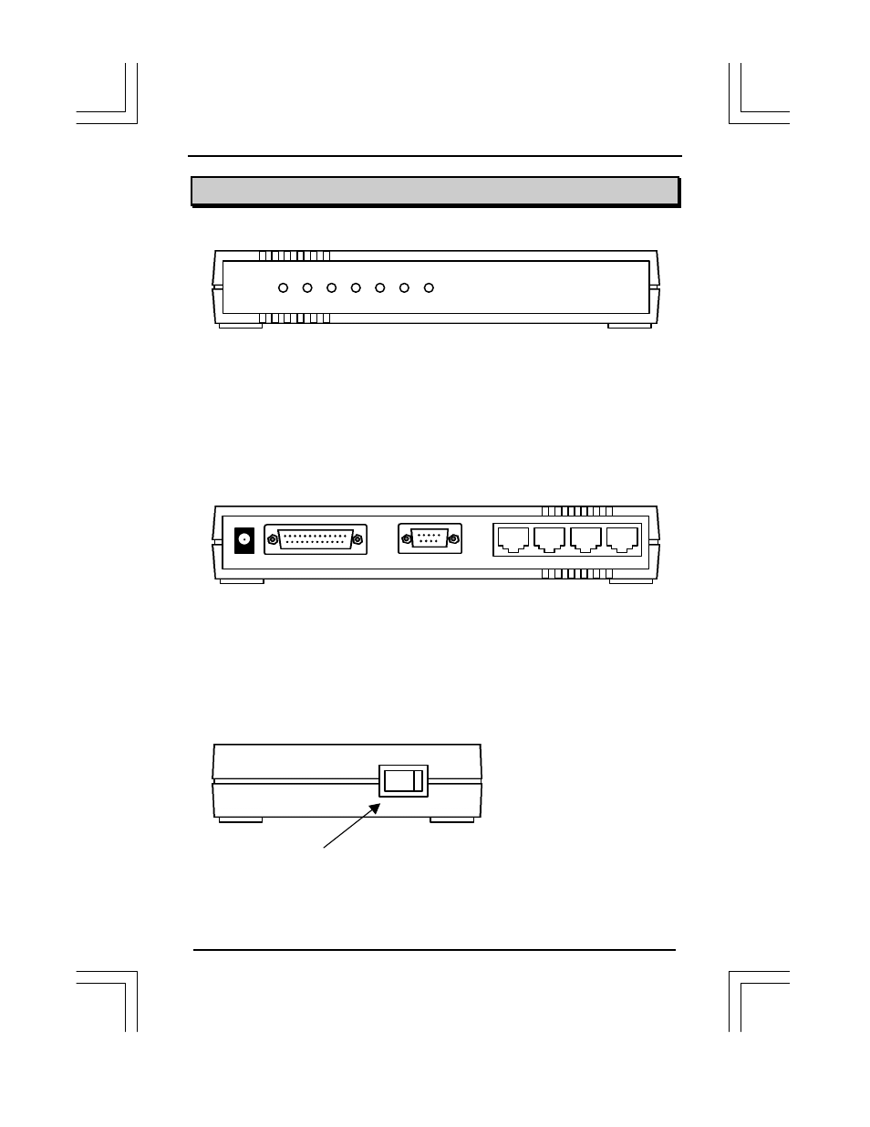
2.2 Your ThinConnect4
l Front Panel
Monitor LED: Shows ThinConnect4 working status.
S1
Light when serial port 1 is sending/receiving data.
S2
Light when serial port 2 is sending/receiving data.
L1
Light when 10BASE-T port 1 is confirming link or receiving data.
L2
Light when 10BASE-T port 2 is confirming link or receiving data.
L3
Light when 10BASE-T port 3 is confirming link or receiving data.
L4
Light when 10BASE-T port 4 is confirming link or receiving data.
PWR
Light when ThinConnect4 is powered on.
l Rear of ThinConnect4 (Connectors)
T1
Port 1: Connects to Ethernet adapter or HUB through 10BASE-T cable.
T2
Port 2: Connects to Ethernet adapter or HUB through 10BASE-T cable.
T3
Port 3: Connects to Ethernet adapter or HUB through 10BASE-T cable.
T4
Port 4: Connects to Ethernet adapter or HUB through 10BASE-T cable.
S1
Serial Port 1: Connects to MODEM or TA.
S2
Serial Port 2: Connects to MODEM or TA.
9 VAC
Power connector: Connects to the AC adapter in the package.
l Right Side of ThinConnect4
Power
Switch: ThinConnect4 power on/off switch.
End of 2.2 Your ThinConnect4
PWR L1 L2 L3 L4 S1 S2
9VAC
S2
S1
T4 T3 T2 T1
OFF ON