Introduction – Magnum Energy MS-AEJ Series User Manual
Page 8
© 2007 Magnum Energy Inc
Page 2
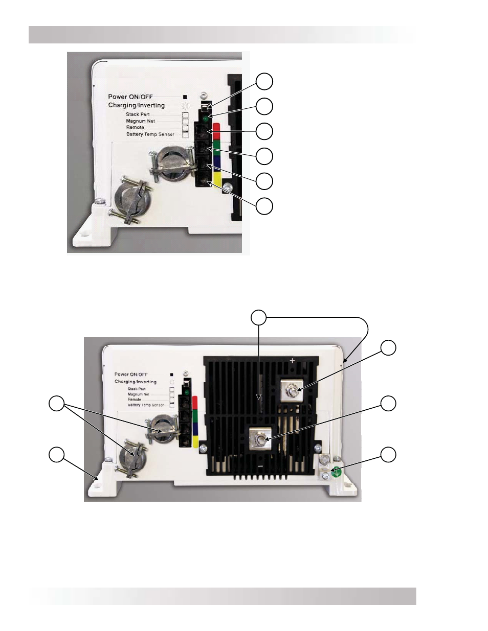
Figure 1-1, Power Switch, Status LED and Accessory Connection Ports
Figure 1-2, Electrical Connection Points
Introduction
AC Entry/Exit
Connections
8
DC Equipment
Ground
Terminal
Positive (+)
DC Terminal
12
Negative (-)
DC Terminal
11
10
Mounting
Flange
Intake
Air Vents
(and on right side)
7
9
P ow er ON /OF F S w itch
S tatus (C harging/Inverting) LE D
S tack P ort
(red label)
M agnum N et P ort
(green label)
R em ote P ort
(blue label)
B attery T em p S ensor P ort
(yellow label)
1
2
3
4
5
6