Installation – Magnum Energy MS-AEJ Series User Manual
Page 29
Page 23
© 2007 Magnum Energy Inc.
2.4.3 Recommended GFCI (Ground Fault Circuit Interruption) Breakers
Some electrical safety codes require the use of GFCI’s. In compliance with UL standards, Magnum
Energy has tested the following GFCI’s and fi nd that they function properly when connected to
the inverter’s AC output:
Shock Sentry
TM
#XGF15V-SP
Leviton Smart Lock #8899-A
Hubbel #GF520EMBKA
WARNING: Risk of electric shock. Use only the ground-fault circuit interrupter [receptacle(s)
or circuit breaker(s)] specifi ed in this manual. Other types may fail to operate properly
when connected to this inverter equipment.
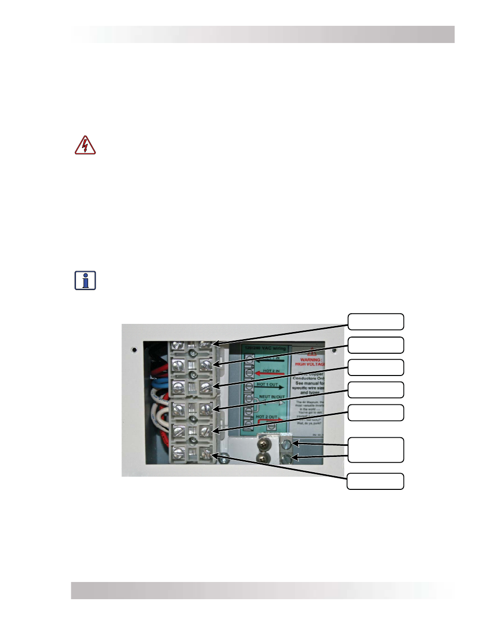
2.4.4 AC Input and Output Wiring Connections
The inverter has a six-connection AC terminal block and two AC ground terminals to connect the
Inverter’s AC input and output wiring. To access and view the AC terminal block and ground termi-
nals, remove the two Phillips screws holding the AC access cover plate (see fi gure 1-3, item 15).
Each connection on the AC terminal block is rated for 105°C and can accept one #18 to #2 AWG
(0.82 to 33.6 mm
2
) CU stranded wire; or two #14 to #8 AWG (2.1 to 8.7 mm
2
) CU stranded wires.
Each connection uses a 1/4-28 screw and the maximum tightening torque is 32 in lbf (3.6 Nm).
Each AC ground terminal can accept one #14 to #6 AWG (2.1 to 13 mm
2
) stranded. Recommended
tightening torque is 45 in lbf (5.1 Nm).
Info: The two neutral terminals are common to each other and can be used in any combi-
nation or order. In a residential application, it is often easier to only connect one AC neutral
wire to the inverter and make the other neutral connections at a central point such as in
the AC electrical panel.
Figure 2-12, AC Terminal Block
A C H OT 2 OU T
A C N E U TR A L
A C H OT 1 IN
A C H OT 2 IN
A C H OT 1 OU T
A C N E U TR A L
A C GR OU N D S
(x 2)
Installation