Magnum Energy MS-AEJ Series User Manual
Page 25
Page 19
© 2007 Magnum Energy Inc.
5 ft or less
5 to 10 ft
10 to 15 ft
MS4024AE
#2/0 AWG x 2
#4/0 AWG x 2
not recommended
MS4448AE
#2/0 AWG
#4/0 AWG
#4/0 AWG x 2
Minimum Recommended DC Wire Size (one way)*
Table 2-4, DC Wire Size For Increased Distance
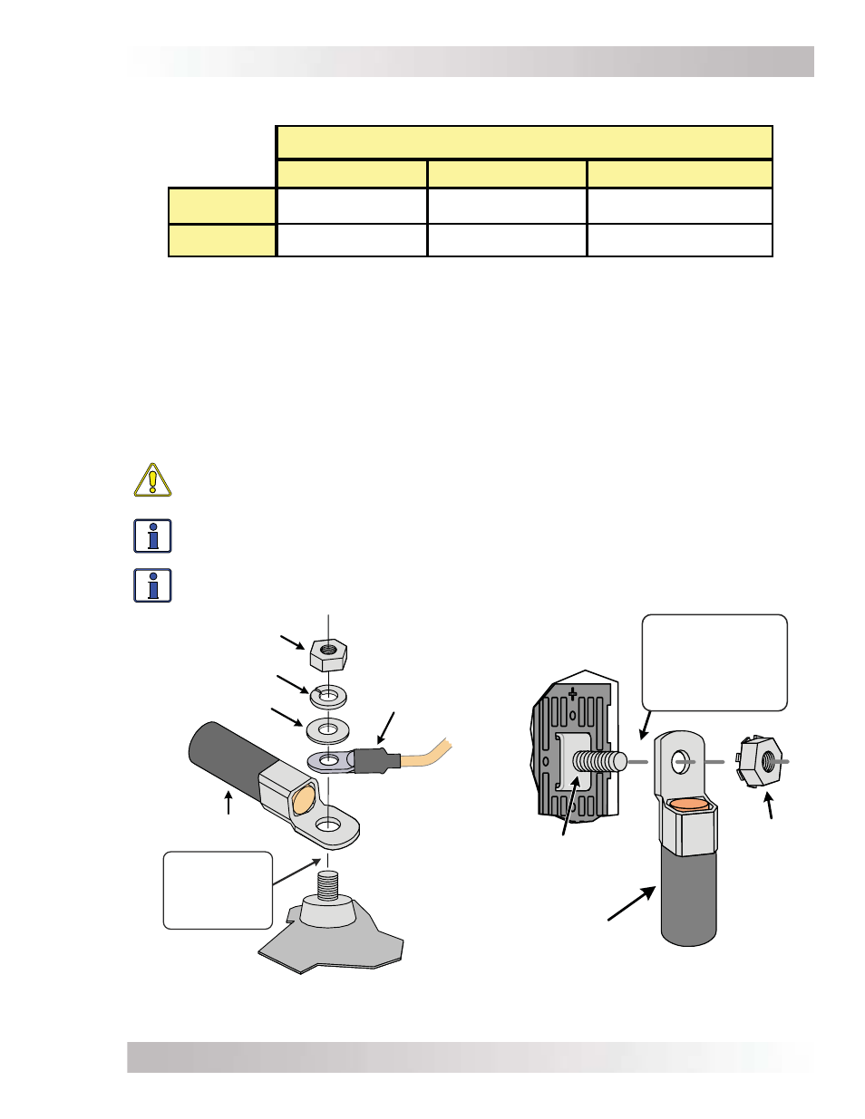
Figure 2-9, Battery Hardware Installation
Figure 2-10, Inverter DC Hardware
Installation
battery cable
(w ith ring lug)
nut
split w asher
flat w asher
Battery
T em perature
Sensor
battery
post
C A U T ION:
Ensure nothing is
placed betw een
cable ring lug and
battery post.
5/16 -18
Kep nut
battery cable
(w ith ring lug)
Inverter D C
term inal
(5/16 -18 bolt,
5/8" length)
C A U T ION:
Ensure nothing is
placed betw een
D C term inal
and ring lug.
2.3.3 DC Cable Connections
Do not put anything between the DC cable ring lug and the battery terminal post or the fl at metal
part of the inverter’s DC terminal. When connecting the DC cable to the battery or inverter DC
terminals, the cable should be placed directly against the inverter or battery terminals. Incorrectly
installed hardware causes a high resistance connection which could lead to poor inverter/charger
performance and may melt the cable and terminal connections.
Follow fi gures 2-9 and 2-10 on how to connect the DC cables and stack the hardware correctly.
Tighten the terminal connections from 10 to 12 ft lbf (13.6 to 16.3 Nm).
CAUTION: The DC terminal and Kep nuts are made of stainless steel which have a high
likelihood of seizure. To help prevent the bolt and nut from seizing - causing the bolts to
strip or snap/break-off - the use of anti-seize lubricant is highly recommended.
Info: If antioxidant grease or spray is used, apply it after all the connections have been
made and are properly tighten.
Info: A 1/2-inch wrench or socket is used to tighten the 5/16 SAE Kep nuts.
* Copper wire rated with 90°C (194°F) insulation at an ambient temperature of 30°C (86°F).
Installation