Installing the inverter, Authorised electrician 7.4.1.1 wiring diagram, Nl2 l1 – KACO Powador 3200 - 6600 User Manual
Page 26
EN
EN
Installing the inverter
Page 26
Operating Instructions for Powador 3200-6600_EN
Authorised electrician
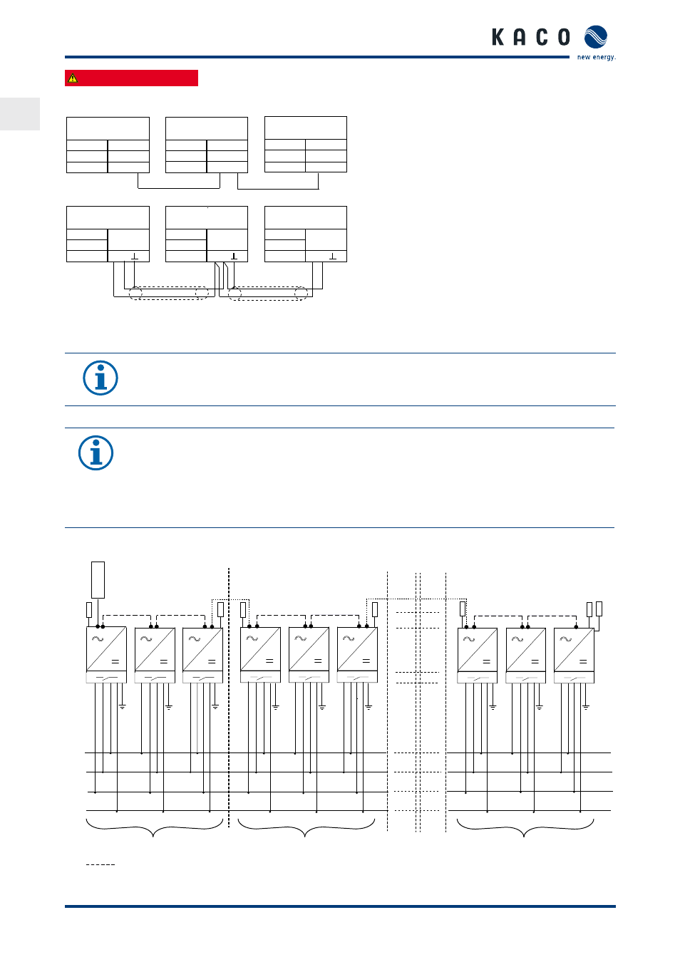
7.4.1.1 Wiring diagram
KACO
Inverter
KACO
Inverter
KACO
Inverter
KACO
Inverter
KACO
Inverter
KACO
Inverter
CAN (Twisted Pair) with-
out RS485 conductor
CAN (Twisted Pair) without
RS485 conductor
Figure 20: SYM bus wiring diagram in group of three
NOTE
When a patch cable with an RJ45 plug is used, an RS485 connection, which is required for a proLOG
connection, is established at the same time.
7.4.1.2 Wiring diagram for park operation (only relevant for series 6600 inverters)
NOTE
Depending on the ARM Software Version, connection in groups of three is required.
From version 4.92 (package version 1.15), the phase unbalanced load monitoring is automatic!
The termination is only carried out here on the terminal unit of the inverter chain.
Up to version 4.91, one of the three connection options must be used. The termination for the CAN
bus must be performed in groups of three!
1. option
The maximum patch cable length for each group of three is 100 m (total length of the inverter chain max. 1200 m)
Group of 3
Patch cable (CAN/RS485)
Group of 3
Group of 3
Term
SYM-BUS
CAN
RJ45
ON
CAN CAN
Term
SYM-BUS
CAN
RJ45
OFF
CAN CAN
Term
SYM-BUS
CAN
RJ45
ON
CAN CAN
Term
CAN
ON
CAN
H L
Term
CAN
OFF
CAN
Term
CAN
ON
CAN
H L
H L
RS485
RS485
RS485
PR
OL
OG
Ra*
Ra* Ra*
Ra*
Ra*
Ra* R
RS485
N
L2
L1
WR 1
WR 2
WR 3
WR 4
WR 5
WR 6
WR 28
WR 29
WR 30
L3
** ** ** **
** ** ** **
** ** ** **
** ** ** **
** ** ** **
** ** ** **
** ** ** **
** ** ** **
** ** ** **