KACO Powador 3200 - 6600 User Manual
Page 20
EN
EN
Installing the inverter
Page 20
Operating Instructions for Powador 3200-6600_EN
Authorised electrician
The power section has two internal circuit board fuses. They are labelled F2 and F861 on the circuit board.
3200-6600
Fuse
F2 type 179120 5x20 slow-blow
250 V / 0.250 A
F861 type TR5 372 0500 250 V / 0.5 A
Vendor
SIBA
Littelfuse/Wickmann
Overvoltage safety class
DC: III, AC: III
Overvoltage safety category
DC: II, AC: III
1
2
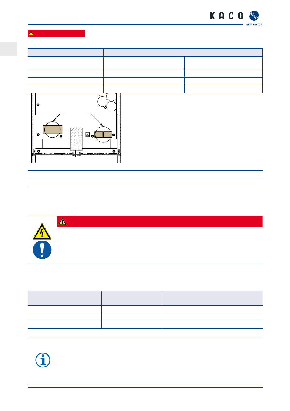
Figure 13: Connection area
Key
1
AC connection terminals
2
DC connection terminals
7.2.1 Connecting the inverter to the power grid
The power connection wires are connected on the right of the connection area ().
A screwdriver (slotted, 3.5 mm) is to be used for the terminals in the inverter.
DANGER
Risk of fatal injury due to electric shock
Severe injury or death will result if the live connections are touched.
›
Switch off all power sources to the inverter before you insert the grid power cable into the unit.
›
Make sure that the device is isolated from the public power supply and the system power supply
before starting work.
Recommended conductor cross-sections and fuse protection of NYM cables for fixed wiring according to VDE
0100 part 430
For cable lengths up to 20 m, use the conductor cross-sections specified in Tabelle 4. Longer cable lengths require
larger conductor cross-sections.
Model
Conductor cross-sec-
tion
Fuse protection: gL safety fuses
Powador 3200, 4200, 4400
2.5 mm²
20 A for 2.5 mm² conductor cross-section
Powador 5500
4.0 mm²
25 A for 4.0 mm² conductor cross-section
Powador 6600
6.0 mm²
35 A for 6.0 mm² conductor cross-section
Table 4:
Recommended conductor cross-sections and fuse protection of NYM cables
NOTE
When the line resistance is high (i.e. long grid-side cables), the voltage at the grid terminals of the
inverter will increase during feed-in to the grid. The inverter monitors this voltage. If it exceeds the
country-specific grid overvoltage limit value, the inverter switches off.
›
Ensure that the conductor cross-sections are sufficiently large or that the cable lengths are suffi-
ciently short.