4 limiting during asymmetric feed to the grid, Limiting during asymmetric feed, To the grid – KACO Powador 3200 - 6600 User Manual
Page 25
EN
Installing the inverter
Page 25
Operating Instructions for Powador 3200-6600_EN
Authorised electrician
Properties of the RS485 data line
Maximum length of the RS485
bus line
The maximum allowed length of the RS485 bus is 1200 m.
This length can be reached only under optimum conditions.
Cable lengths exceeding 500 m generally require a repeater or a hub.
Maximum number of
connected bus devices
31 inverters + 1 data monitoring unit
Data line
Twisted, shielded. Recommendations:
LI2YCYv (twisted pair) black for laying cable outside and in the ground, 2 x 2 x 0.5
LI2YCY (twisted pair) grey for dry and moist indoor spaces, 2 x 2 x 0.5
NOTE
Different manufacturers do not always interpret the standard on which the RS485 protocol is based
in the same way. Note that the wire designations (- and +) for wires A and B can vary between manu-
facturers.
NOTE
Calculating efficiency by measuring the current and voltage values can lead to misleading results
due to the tolerances of the measurement devices. The sole purpose of these measured values is to
monitor the basic operation of the system.
Connecting the RS485 bus
"
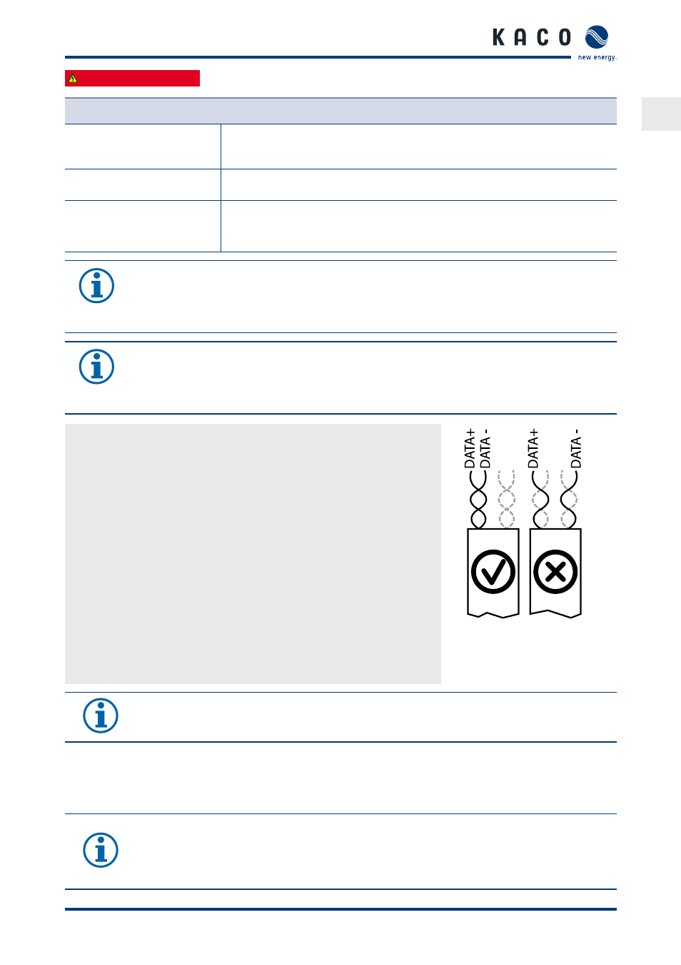
To prevent interference during data transmission:
•
Observe the wire pairing when connecting DATA+ and DATA- (see Bild 19)
•
Do not install RS485 bus lines in the vicinity of live DC/AC cables.
1. Unscrew the cable fitting.
2. Thread the connection cables through the cable fitting.
3. Connect the connection cables to the corresponding connection termi-
nals (see Bild 16 auf Seite 23).
4. The following must be connected to all inverters and to the data monitor
unit in the same way:
–
Wire A (-) with wire A (-) and
–
Wire B (+) with wire B (+) (see Bild 17 auf Seite 24)
5. Tighten the cable fitting.
6. Activate the terminating resistor on the terminal unit.
Figure 19: RS485 bus: Assignment of
twisted-pair wires
NOTE
When using the RS485 bus system, assign a unique address to every bus device (inverter, sensor) and
terminate the terminal units (see the “Settings” menu).
7.4
Limiting during asymmetric feed to the grid
7.4.1 Connecting CAN bus
NOTE
The inverters communicate information on the symmetry of the phase feed over the CAN communi-
cations interface.
Every inverter calculates the maximum permitted feed-in power for its phase, both in total and
considering the asymmetry.