1 connecting the fault signal relay, 2 connecting the s0 output, 3 connecting the rs485 bus – KACO Powador 3200 - 6600 User Manual
Page 24: Installing the inverter, Authorised electrician, Maximum contact load, 1 wiring diagram
EN
EN
Installing the inverter
Page 24
Operating Instructions for Powador 3200-6600_EN
Authorised electrician
7.3.1 Connecting the fault signal relay
The contact is designed as an N/O contact and is labelled “ERR” on the circuit board.
Maximum contact load
DC
30 V / 1 A
AC
250 V / 1 A
Connecting the fault signal relay
1. Unscrew the cable fitting.
2. Thread the connection cables through the cable fitting.
3. Attach the connection cables to the connection terminals.
4. Tighten the cable fitting.
7.3.2 Connecting the S0 output
An S0 pulse output is located on the communication board. Use this output to control accessories such as a large
display, for example. The pulse rate of the output is adjustable.
Connecting the S0 output
1. Unscrew the cable fitting.
2. Thread the connection cables through the cable fitting.
3. Attach the connection cables to the connection terminals.
4. Tighten the cable fitting.
NOTE
Ensure that the wires are properly connected. Communication is not possible if the wires are
reversed.
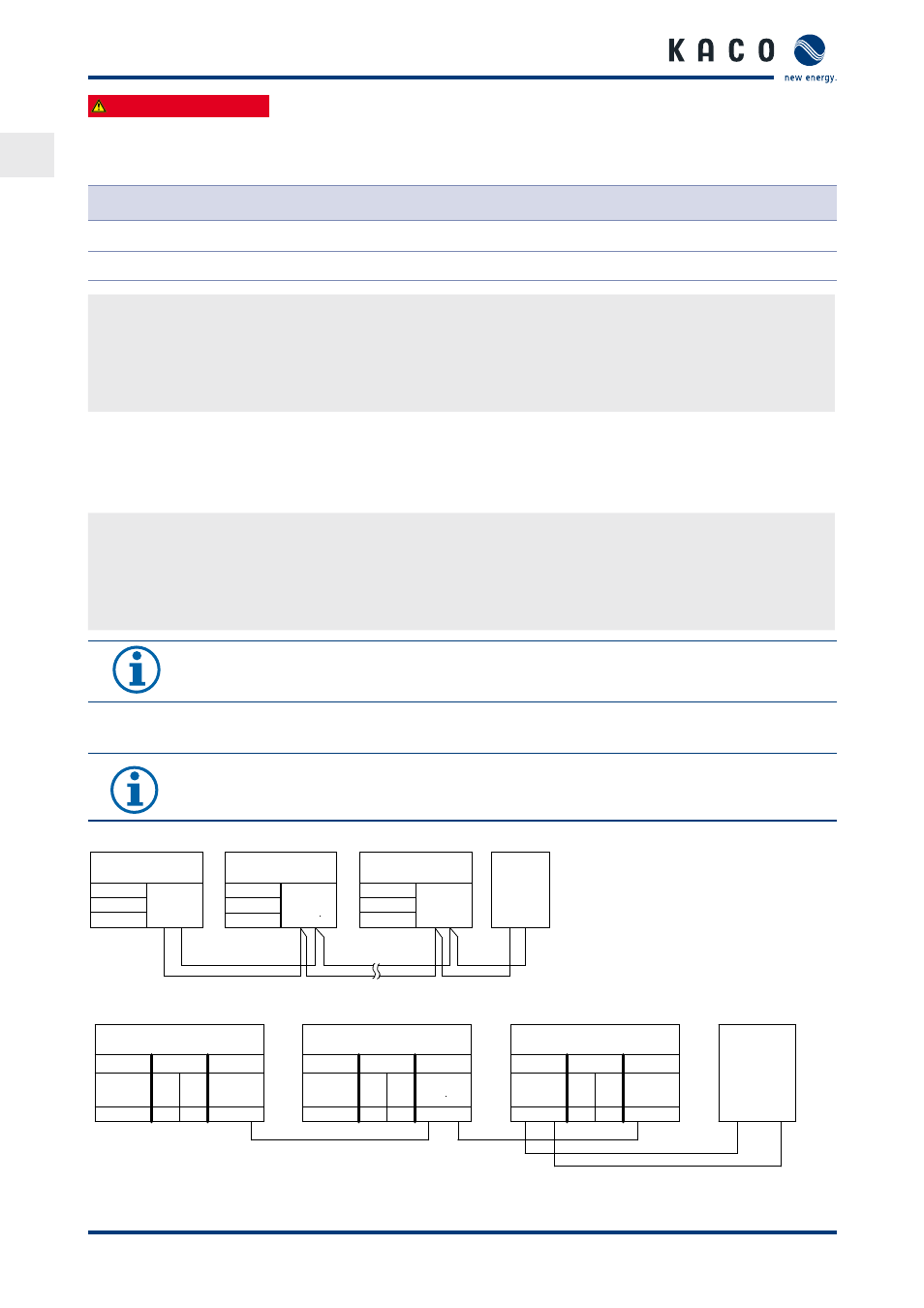
7.3.3 Connecting the RS485 bus
NOTE
Ensure that the A and B wires are properly connected. Communication is not possible if the wires are
reversed.
7.3.3.1 Wiring diagram
KACO
Inverter
KACO
Inverter
KACO
Inverter
KACO
Monitor-
ing
system
Figure 17: RS485 interface wiring diagram
KACO
Inverter
KACO
Inverter
KACO
Inverter
KACO
monitor-
ing system
Figure 18: RS485 interface wiring diagram with CAN (RJ45) connection
Term
RS485
RS485
ON
A B
Term
RS485
RS485
OFF
Term
RS485
RS485
OFF
A B
A B
Term
ON
ON
A
B
SYM-Bus
CAN
CAN
A
B
RS485
RS485
CAN
RJ45
RS485
CAN
CAN
Term
A
OFF
RS485
SYM-Bus
RJ45
CAN
OFF
B
RS485
ON
SYM-Bus
RS485
Term
CAN
B
OFF
CAN
RJ45
CAN
A
Patch-Cable