Fault detection, Fault displays, causes, and possible solutions, 2 fault detection – Yaskawa CIMR-PUxA User Manual
Page 135: Data displayed varies by the type of fault, Refer to fault displays, causes, and possible, For more information
5.2 Fault Detection
u
Fault Displays, Causes, and Possible Solutions
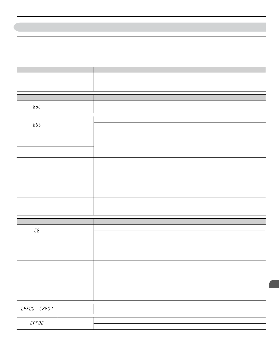
Faults are detected for drive protection, and cause the drive to stop while triggering the fault output terminal MA-MB-MC.
Remove the cause of the fault and manually clear the fault before attempting to run the drive again.
Table 5.2 Detailed Fault Displays, Causes, and Possible Solutions
Digital Operator Display
Fault Name
bAT
bAT
Digital Operator Battery Voltage Low
Cause
Possible Solution
The digital operator battery is low
Replace the digital operator battery.
Digital Operator Display
Fault Name
boL
Braking Transistor Overload Fault
The braking transistor reached its overload level.
bUS
Option Communication Error
• The connection was lost after establishing initial communication.
• Only detected when the run command frequency reference is assigned to an option card.
Cause
Possible Solution
No signal was received from the PLC
• Check for faulty wiring.
• Correct the wiring.
• Check for disconnected cables and short circuits and repair as needed.
Faulty communications wiring or an existing
short circuit
Communication data error occurred due to
noise
• Check the various options available to minimize the effects of noise.
• Counteract noise in the control circuit, main circuit, and ground wiring.
• Ensure that other equipment such as switches or relays do not cause noise. Use surge absorbers if
necessary.
• Use only recommended cables or other shielded line. Ground the shield on the controller side or the
drive input power side.
• Separate all communication wiring from drive power lines. Install an EMC noise filter to the drive
power supply input.
The option card is damaged
Replace the option card if there are no problems with the wiring and the error continues to occur.
The option card is not properly connected to
the drive
• The connector pins on the option card do not line up properly with the connector pins on the drive.
• Reinstall the option card.
Digital Operator Display
Fault Name
CE
MEMOBUS/Modbus Communication Error
Control data was not received for the CE detection time set to H5-09.
Cause
Possible Solution
Faulty communications wiring or an existing
short circuit
• Check for faulty wiring.
• Correct the wiring.
• Check for disconnected cables and short circuits and repair as needed.
Communication data error occurred due to
noise
• Check the various options available to minimize the effects of noise.
• Counteract noise in the control circuit, main circuit, and ground wiring.
• Use only recommended cables or other shielded line. Ground the shield on the controller side or the
drive input power side.
• Ensure that other equipment such as switches or relays do not cause noise. Use surge suppressors if
required.
• Separate all communication wiring from drive power lines. Install an EMC noise filter to the drive
power supply input.
or
CPF11 to CPF14
CPF16 to CPF19
Control Circuit Error
CPF02
A/D Conversion Error
An A/D conversion error or control circuit error occurred.
5.2 Fault Detection
YASKAWA ELECTRIC TOEP YAIP1U 01B YASKAWA AC Drive - P1000 Quick Start Guide
135
5
Troubleshooting