Fan and pump application preset details, 12 fan and pump application preset details – Yaskawa CIMR-PUxA User Manual
Page 128

4.12 Fan and Pump Application Preset Details
n
b1-04: Reverse Operation Selection
Enables and disables Reverse operation. For some applications, reverse motor rotation is not appropriate and may cause
problems (e.g., air handling units, pumps, etc.).
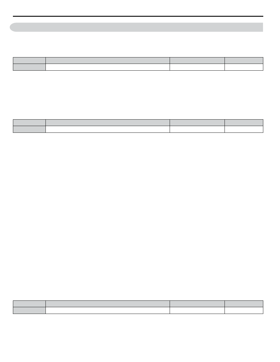
No.
Parameter Name
Setting Range
Default
b1-04
Reverse Operation Selection
0, 1
0
Setting 0: Reverse operation enabled
Possible to operate the motor in both forward and reverse directions.
Setting 1: Reverse operation disabled
Drive disregards a Reverse run command or a negative frequency reference.
n
b5-12: PID Feedback Loss Detection Selection
Enables or disables the feedback loss detection and sets the operation when a feedback loss is detected.
No.
Parameter Name
Setting Range
Default
b5-12
PID Feedback Loss Detection Selection
0 to 5
0
Setting 0: Digital Output Only
A digital output set for “PID feedback low” (H2-oo = 3E) will be triggered if the PID feedback value is below the detection
level set to b5-13 for the time set to b5-14 or longer. A digital output set for “PID feedback high” (H2-oo = 3F) will be
triggered if the PID feedback value is beyond the detection level set to b5-36 for longer than the time set to b5-37. Neither a
fault nor an alarm is displayed on the digital operator and the drive will continue operation. The output resets when the feedback
value leaves the loss detection range.
Setting 1: Feedback Loss Alarm
If the PID feedback value falls below the level set to b5-13 for longer than the time set to b5-14, a “FBL - Feedback Low”
alarm will be displayed and a digital output set for “PID feedback low” (H2-oo = 3E) will be triggered. If the PID feedback
value exceeds the level set to b5-36 for longer than the time set to b5-37, a “FBH - Feedback High” alarm will be displayed
and a digital output set for “PID feedback high” (H2-oo = 3F) will be triggered. Both events trigger an alarm output
(H1-oo = 10). The drive will continue operation. The alarm and outputs reset when the feedback value leaves the loss detection
range.
Setting 2: Feedback Loss Fault
If the PID feedback value falls below the level set to b5-13 for longer than the time set to b5-14, a “FbL - Feedback Low”
fault will be displayed. If the PID feedback value exceeds the level set to b5-36 for longer than the time set to b5-37, a “FbH
- Feedback High” fault will be displayed. Both events trigger a fault output (H1-oo = E) and cause the drive to stop the
motor.
Setting 3: Digital Output Only, even if PID Is Disabled by Digital Input
Same as b5-12 = 0. Detection remains active when PID is disabled by a digital input (H1-oo = 19).
Setting 4: Feedback Loss Alarm, even if PID Is Disabled by Digital Input
Same as b5-12 = 1. Detection remains active when PID is disabled by a digital input (H1-oo = 19).
Setting 5: Feedback Loss fault, even if PID Is Disabled by Digital Input
Same as b5-12 = 2. Detection remains active when PID is disabled by a digital input (H1-oo = 19).
n
b5-19: PID Setpoint Value
Used as the PID setpoint if parameter b5-18 = 1.
No.
Name
Setting Range
Default
b5-19
PID Setpoint Value
0.00 to 100.00%
0.00%
4.12 Fan and Pump Application Preset Details
128
YASKAWA ELECTRIC TOEP YAIP1U 01B YASKAWA AC Drive - P1000 Quick Start Guide
