F (-10 to +50 – Yaskawa VS mini J7 Series User Manual
Page 80
80
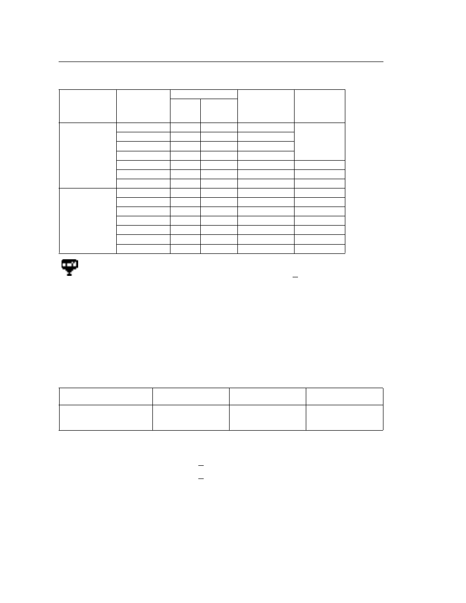
Carrier Frequency Varies According to Inverter Capacity (kVA).
(3) Carrier frequency can be automatically reduced to 2.5 kHz when (n75) is set
to 1 and the following conditions are satisfied.
Output frequency < 5Hz
Output frequency > 100%
Factory Setting (n75) is 0 (disabled)
Voltage Class
Capacity
hp(kW)
Initial Setting
Maximum
Continuous
Output Current
(A)
Reduced
Current (A)
*1
Setting
Carrier
Frequency
200V
Single-phase
3-phase
0.13 (0.1)
4
10kHz
0.8
–
0.25 (0.2)
4
10kHz
1.6
0.5 (0.4)
4
10kHz
3.0
1 (0.75)
4
10kHz
5.0
2 (1.5)
3
7.5kHz
8.0
7.0
3 (2.2)
3
7.5kHz
11.0
10.0
5 (3.7)
3
7.5kHz
17.5
16.5
400V
3-phase
0.25 (0.2)
3
7.5kHz
1.2
1.0
0.5 (0.4)
3
7.5kHz
1.8
1.6
1 (0.75)
3
7.5kHz
3.4
3.0
2 (1.5)
3
7.5kHz
4.8
4.0
3 (2.2)
3
7.5kHz
5.5
4.8
4 (3.0)
3
7.5kHz
7.2
6.3
5 (3.7)
3
7.5kHz
9.2
7.6
(1) Reduce continuous output current by changing carrier frequency to a
setting of 4 (10 kHz) for 200V class inverters (size > 1.5kW) and all 400V
class inverters. Refer to the table above for the reduced current.
[Operation Condition]
•
Input power supply voltage: 3-phase 200 to 230V (200V class)
Single-phase 200 to 240V (200V class)
3-phase 380 to 460V (400V class)
•
Ambient temperature:
14 to 122
o
F (-10 to +50
o
C)
(2) If the wiring distance is long (approx. 50 meters), reduce the inverter car-
rier frequency as described below.
Wiring Distance between
Inverter and Motor
Up to 50m
Up to 100m
More than 100m
Carrier frequency
(n46 setting)
10kHz or less
(n46=1, 2, 3, 4,
7, 8, 9)
5kHz or less
(n46=1, 2,
7, 8, 9)
2.5kHz or less
(n46=1, 7, 8, 9)