On : blinking : off – Yaskawa VS mini J7 Series User Manual
Page 104
104
< Corrective Actions of Models with Digital Operator >
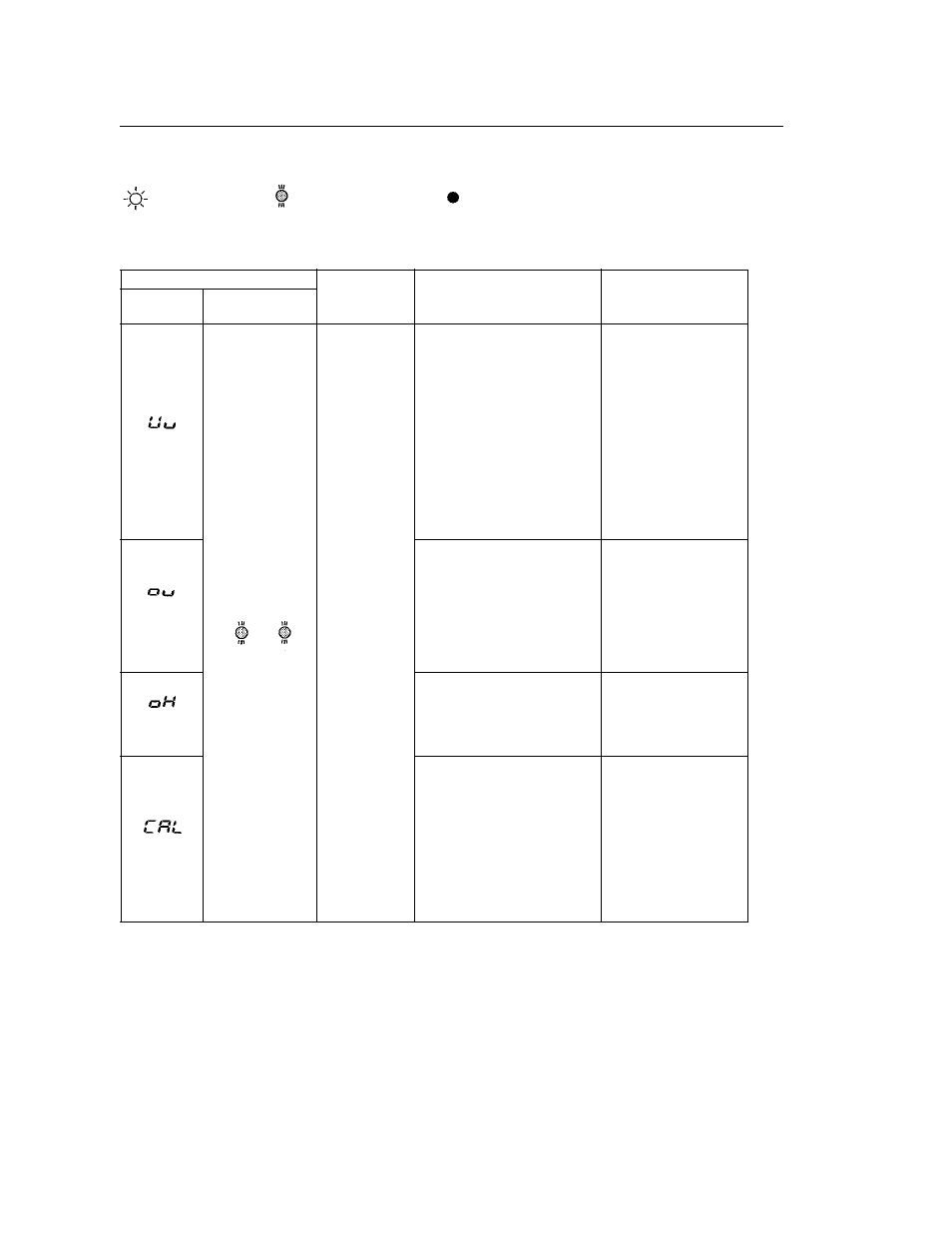
Alarm Display and Contents
Alarm Display
Inverter
Status
Explanation
Causes and
Corrective Actions
Digital
Operator
RUN ALARM
(Green) (Red)
Blinking
Warning
Fault contacts
do not change
state.
UV (Main circuit low voltage)
Main circuit DC voltage drops
below the low-voltage
detection level while the
inverter output is OFF.
200V: Main circuit DC voltage
become lowered below
approx. 200V (160V for
single phase)
400V:Main circuit DC voltage
become lowered below
approx. 400V.
Check the following:
• Power supply
voltage
• Main circuit power
supply wiring is
connected.
• Terminal screws are
securely tightened.
Blinking
OV (Main circuit over voltage)
Main circuit DC voltage
exceeds the over voltage
detection level while the
inverter output is OFF.
Detection level: approx. 410V
or more (approx. 820V for
400V class).
Check the power
supply voltage.
Blinking
OH (Cooling fin overheat)
Intake air temperature rises
while the inverter output is
OFF.
Check the intake air
temperature.
Blinking
CAL (MEMOBUS
communications waiting)
Correct data has not been
received from the PLC when
the parameters n02
(operation command
selection) is 2 or n03
(frequency reference
selection) is 6, and power is
turned ON.
Check communication
devices and
transmission signals.
: ON
: Blinking
: OFF