Wiring, Wiring instructions, Wire and terminal screw sizes – Yaskawa VS mini J7 Series User Manual
Page 39: Control circuit
39
5. WIRING
• Wiring Instructions
(1) Always connect the power supply via a molded-case circuit breaker (MCCB) to the
power input terminals R/L1, S/L2, and T/L3 (R/L1, S/L2 for single-phase). Never
connect the power supply to U/T1, V/T2, W/T3,-,+1 or +2.
The single-phase (200V class) inverter can be connected to a 200V 3-phase input.
However, when a single-phase supply is used, never use the terminal T/L3 for other
purposes.
Inverter Power Supply Connection Terminals
(2) Connect the motor wiring to terminals U, V, and W on the main circuit output side
(bottom of the inverter).
(3) If the wiring distance between inverter and motor is long, reduce the inverter
carrier frequency. For details, refer to “Reducing motor noise or leakage current
(n46)” on page 79.
(4) Control wiring must be less than 164ft(50m) in length and separate from the power
wiring. Use twisted-pair shielded wire when inputting the frequency signal
externally.
(5) Tighten the screws on the main circuit and control circuit terminals.
(6) Do not connect or disconnect wiring, or perform signal checks while the power
supply is turned ON.
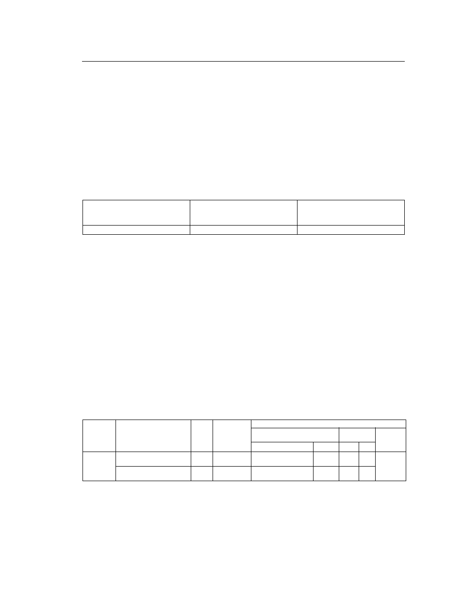
• Wire and Terminal Screw Sizes
1. Control Circuit
200V 3-phase Input Power Supply
Specification Product
CIMR-J7!!2!!!
200V Single Input Power Supply
Specification Product.
CIMR-J7!!B!!!
400V 3-phase Input Power Supply
Specification Product.
CIMR-J7!!4!!!
Connect to R/L1, S/L2, T/L3
Connect to R/L1, S/L2
Connect to R/L1, S/L2, T/L3
Model
Terminal Symbol
Screw
Tightening
Torque
lb • in (N • m)
Wire
Applicable size
Recommend
size
Type
mm
2
AWG
mm
2
AWG
Common
to
all models
MA, MB, MC
M3
4.44 to 5.33
(0.5 to 0.6)
twisted wire 0.5 to 1.25
single
0.5 to 1.25
20 to 16
20 to 16
0.75
18
Shielded
wire or
equivalent
S1 to
S5,SC,FS,FR,FC,AM,AC
M2
1.94 to 2.21
(0.22 to 0.25)
twisted wire 0.5 to 0.75
single
0.5 to 1.25
20 to 18
20 to 16
0.75
18