SMA SB 240 User Manual
Page 22
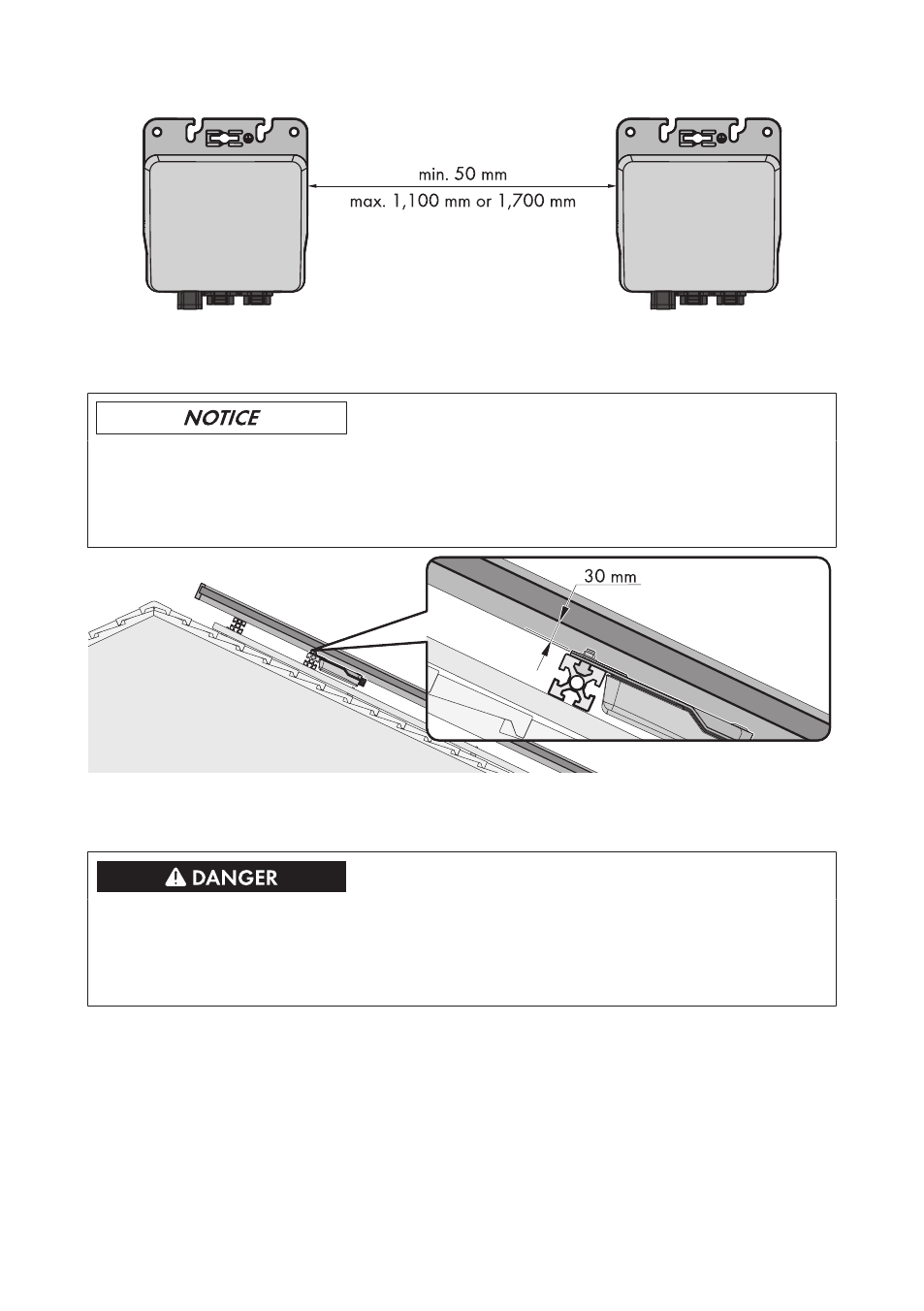
Figure 9: Recommended clearances
Minimum Clearance between Inverter and PV Module Bottom Side:
Damage to the PV module due to insufficient clearance between the inverter and the
PV module bottom side
For roof mounting, the clearance from the inverter to the bottom side of the PV module must be at
least 30 mm. This will prevent the grounding bolt from damaging the PV module.
Figure 10: Minimum clearance of the inverter to the bottom side of the PV module
Permitted Mounting Position:
Electric shock due to ingress of moisture
• During mounting, make sure that the connection area of the inverter remains dry.
As soon as the connector and protective cap are plugged in, the connection area will be
protected from moisture ingress. Thus, the inverter complies with degree of protection IP65.
☐ In order to ensure optimum operation and long electrical endurance of the inverter, install
each inverter centered under the respective connection socket of the PV module.
☐ For installations that are integrated into the building, do not install the inverter directly on the
back side of the PV module. This will prevent the inverter power from being reduced due to
excessive ambient temperature.
5 Mounting
SMA Solar Technology AG
Installation Manual
SMA-SB240-IA-en-12
22