3 led signals, Led signals – SMA SB 240 User Manual
Page 16
Position
Explanation
F
Screw terminal for AC output (utility grid)
Labeling: Grid
G
Pin connector for connecting the network cable (RJ45)
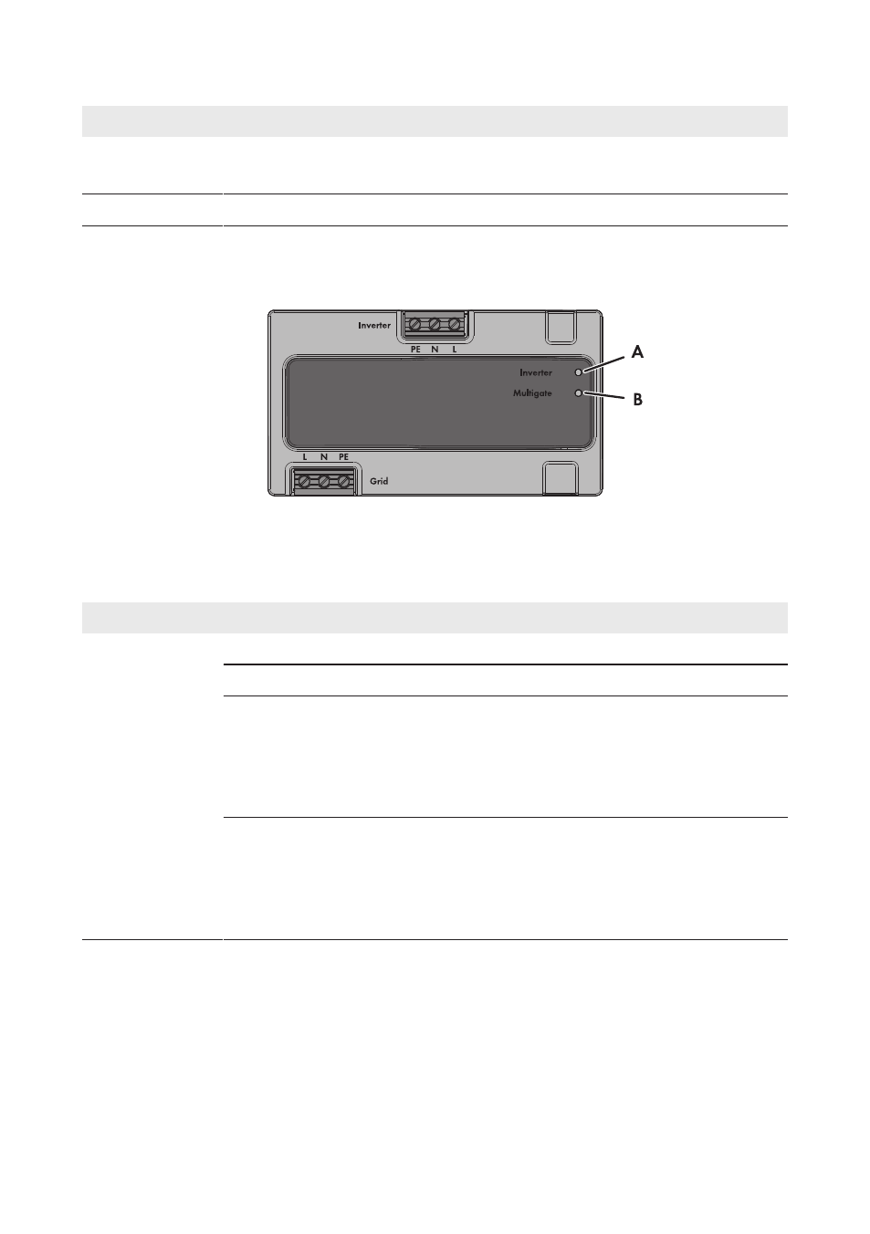
4.3 LED Signals
The LEDs on the Sunny Multigate indicate the operating state of the PV system.
Figure 6: Position of the LEDs on the Sunny Multigate
The upper LED is labeled with Inverter and indicates the operating state of the inverters.
The lower LED is labeled with Multigate and indicates the operating state of the Sunny Multigate.
LED
Status
Explanation
A: LED Inverter
off
The communication with the inverters is not active.
glowing green
The inverters are in operation.
glowing orange
At least one of the connected inverters is in Warning
mode. You will find the detailed error message in Sun-
ny Portal or Sunny Explorer. You can find the cause and
its corrective measure in this document (see Section 11
"Troubleshooting", page 51).
glowing red
At least one of the connected inverters is in Fault mode.
You will find the detailed error message in Sunny Portal or
Sunny Explorer. You can find the cause and its corrective
measure in this document (see Section 11 "Troubleshoot-
ing", page 51).
4 Product Description
SMA Solar Technology AG
Installation Manual
SMA-SB240-IA-en-12
16