Please note while programming, Cycle parameters – HEIDENHAIN iTNC 530 (340 49x-06) Cycle programming User Manual
Page 357
HEIDENHAIN iTNC 530
357
15.5 D
A
TUM FR
OM OUTSIDE OF RECT
A
NGLE (Cy
c
le 41
1, DIN/ISO: G41
1
)
Please note while programming:
Cycle parameters
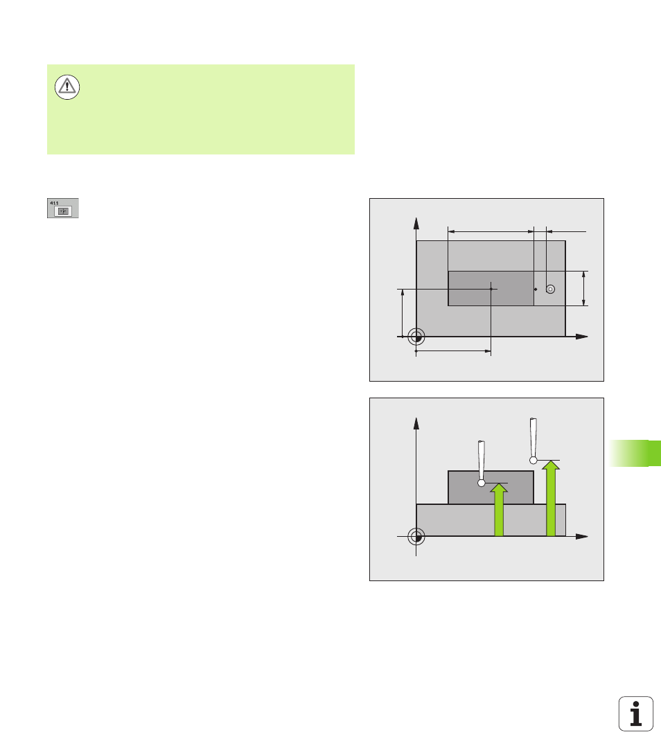
U
Center in 1st axis
Q321 (absolute): Center of the
stud in the reference axis of the working plane. Input
range -99999.9999 to 99999.9999
U
Center in 2nd axis
Q322 (absolute): Center of the
stud in the minor axis of the working plane. Input
range -99999.9999 to 99999.9999
U
First side length
Q323 (incremental): Stud length,
parallel to the reference axis of the working plane
Input range 0 to 99999.9999
U
2nd side length
Q324 (incremental): Stud length,
parallel to the minor axis of the working plane. Input
range 0 to 99999.9999
U
Measuring height in the touch probe axis
Q261 (absolute): Coordinate of the ball tip
center (= touch point) in the touch probe axis in
which the measurement is to be made. Input
range -99999.9999 to 99999.9999
U
Setup clearance
Q320 (incremental): Additional
distance between measuring point and ball tip. Q320
is added to MP6140. Input range 0 to 99999.9999,
alternatively PREDEF
U
Clearance height
Q260 (absolute): Coordinate in the
touch probe axis at which no collision between touch
probe and workpiece (fixtures) can occur. Input range
-99999.9999 to 99999.9999, alternatively PREDEF
Danger of collision!
To prevent a collision between the touch probe and
workpiece, enter high estimates for the lengths of the 1st
and 2nd sides.
Before a cycle definition you must have programmed a
tool call to define the touch probe axis.
X
Y
Q322
Q321
Q324
Q323
MP6140
+
Q320
X
Z
Q261
Q260