14 contours in the xy plane, Reference data in xy plane – HEIDENHAIN SW 688945-03 User Manual
Page 439
HEIDENHAIN CNC PILOT 620/640
439
6.14 Cont
ours in the XY plane
6.14 Contours in the XY plane
In smart.Turn, ICP provides the following contours for machining with
the Y axis:
Complex contours defined with individual contour elements
Figures
Holes
Pattern of figures or holes
Single surface
Polygon
Enter the dimensions of the XY plane contour elements in Cartesian
or polar values. You can switch between them by pressing a soft key
(see table). You can mix Cartesian coordinates and polar coordinates
to define a point.
Reference data in XY plane
The reference data follows the contour definition with individual
contour elements.
You can find the reference dimension ZR and the limit diameter IR
with the "select reference plane" function (see page 418).
ICP generates:
The section code FRONT_Y with the parameters reference
dimension, spindle angle, and limit diameter. The section code is
omitted for nested contours.
A G308 with the parameters contour name and milling depth.
A G309 at the end of the contour description.
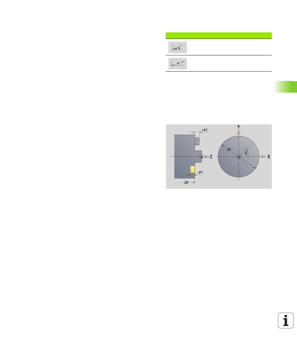
Soft keys for polar coordinates
Switches the field to entering the
angle W.
Switches the field to entering the
radius P.
Reference data of milling operations
ID
Contour name
PT
Milling depth
C
Spindle angle
IR
Limit diameter
ZR
Reference dimension