T-pov usage scenarios – Grass Valley T-POV Bidirectional Robotic User Manual
Page 60
54
Connecting the T-POV System
T-POV Usage Scenarios
T-POV Usage Scenarios
The three scenarios shown represent a small cross-section of the various available
configurations. Please consider these scenarios as samples of how a system might be used
in a real-world application.
The following fiber connection scenarios do not take into account any customized cable
and connector installations you may have at your facility. For assistance regarding more
complex connection situations, contact Grass Valley (see
local authorized dealer.
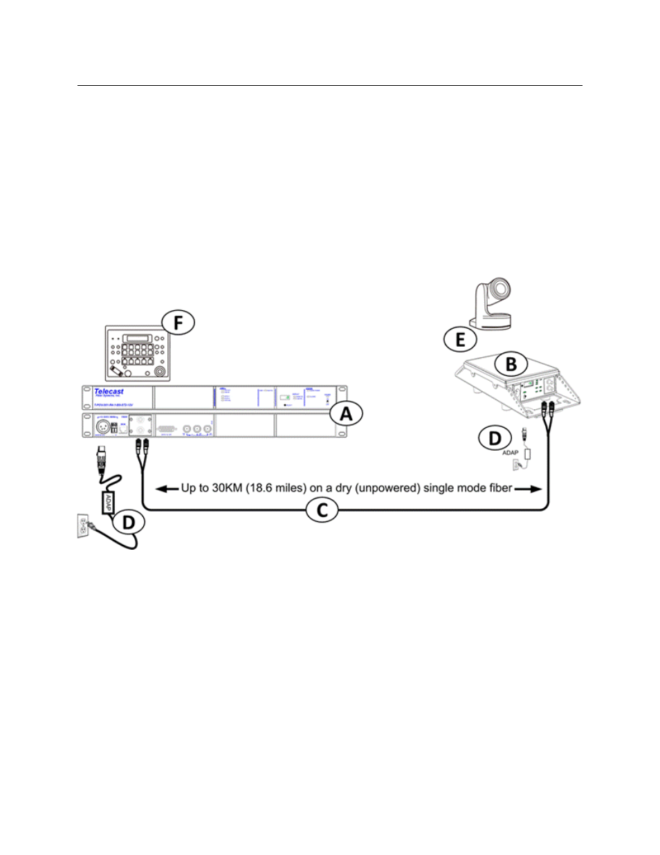
Tactical Fiber between the Base Station and Camera Unit
Fig. 5-1: Tactical Fiber between the Base Station and Camera Unit
Between the Base Station (A) the Camera Unit (B) is a length of Tactical Fiber Cable (C). At
each end of the fiber cable are a set of two ST Connectors.
The Camera Unit and the Base Station are powered by an external 12 Volt power supply (D).
The recommended ADAP-AC-04 is illustrated. The Camera connected to the Camera Unit
must have its own separate power source.
Connected to the Base Station is a Camera Control Unit (CCU) with camera controls and
remote pan and tilt controls (F). Depending on the control unit requirements the
connection to the base station will be either a serial data connection or an Ethernet
connection.
Connected to the Camera Unit is a remote HD Camera (E) mounted on a remotely
controlled pan and tilt unit. Typically the camera will be connected to the T-POV Camera
Unit by an HD-SDI BNC cable and the pan and tilt unit will be connected through either a
serial data connection or an Ethernet Connection.