T-pov 301 multiple unit detail, Area a area b area d – Grass Valley T-POV Bidirectional Robotic User Manual
Page 30
24
T-POV 301 Components
T-POV 301 Multiple Unit Detail
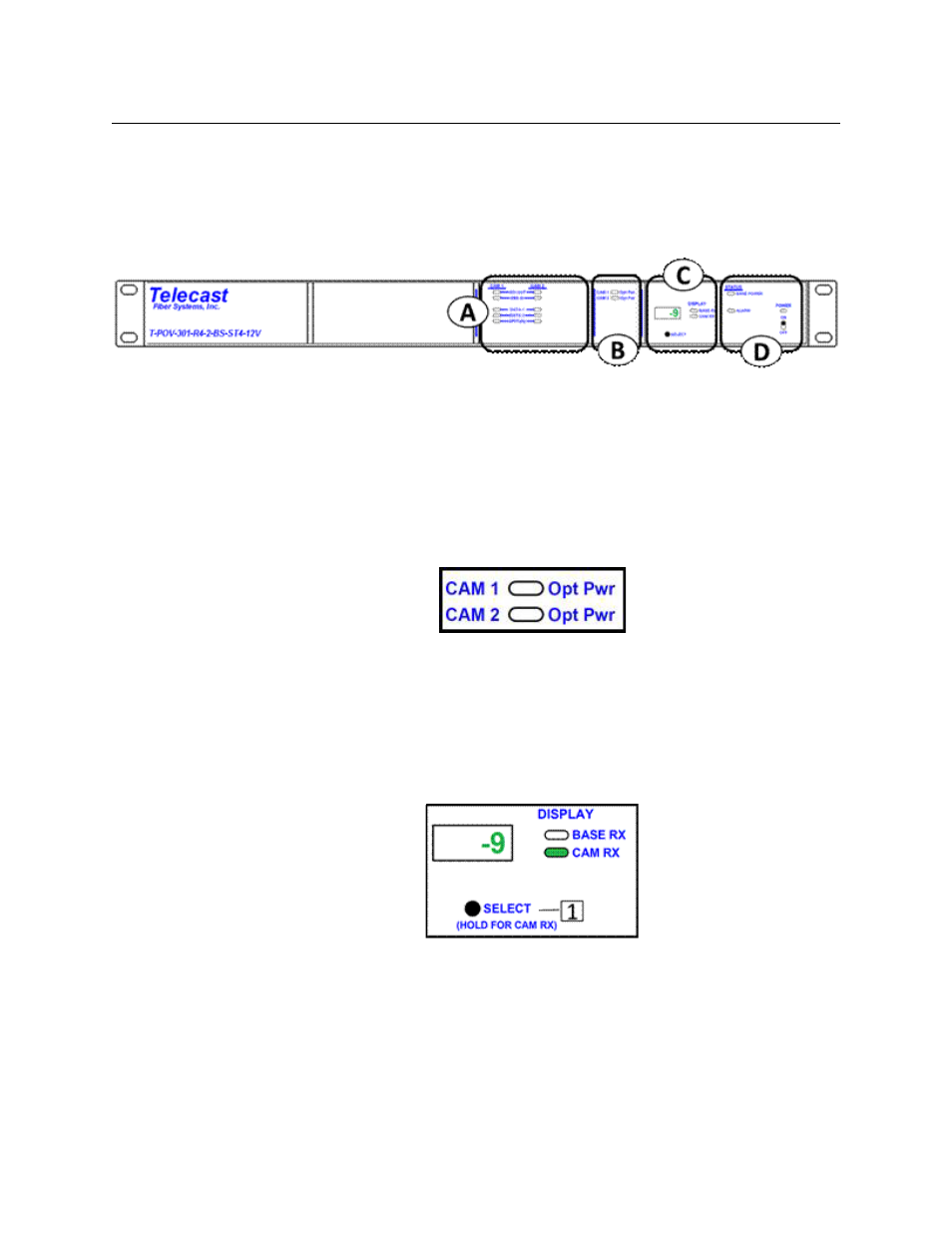
T-POV 301 Multiple Unit Detail
The T-POV 301 Multiple Unit Base Station differs from the single unit model in that there are
additional LED indicator columns for Camera 2 in Area A and additional Optical Power
indicators in Area B. Component operation differences are noted below.
Fig. 3-6: T-POV 301 Multiple Unit Base Station
AREA A
The indicator AREA A in the two unit Base Station operates identically to that of a single unit
model (see
Area A - Signal Indicator LEDs
on page 21). The indicator LEDs monitor functions
independently of each other.
AREA B
Fig. 3-7: T-POV 301 Multiple Unit Base Station -- Area B
The Opt Pwr indicators illuminate as the Select button is toggled through the two Camera
Units. The indicators will light Red if there is no optical connection. A blinking Opt Pwr LED
indicates that a camera link optical power level is being displayed on the Digital Display in
Area C.
AREA D
Fig. 3-8: T-POV 301 Multiple Unit Base Station -- Area D
SELECT button chooses between three modes of operation.
When the Base Station is powered on, Base Station optical power is displayed. The first push
of the SELECT button will select CAM 1; the second push will select CAM 2.
Pushingand holding the SELECT button will enter the diagnostics mode for the device
currently being displayed.