T-pov 301 base unit rear panel detail, Area e - power section and fiber connector(s) – Grass Valley T-POV Bidirectional Robotic User Manual
Page 33
27
T-POV
User Guide
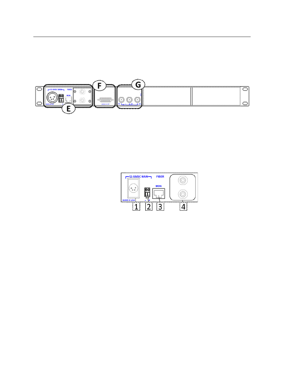
T-POV 301 Base Unit Rear Panel Detail
The Base Unit rear panel Area diagram is repeated for reference. In multi-unit Base Stations
camera one is on the left next to the power and fiber connector section. Camera two is to
the right of camera one and camera three is to the right of camera two (if so equipped).
Fig. 3-11: T-POV 301 Base Station Rear/Connector Panel
The T-POV Base Station Connector Panel has four features:
• E: Power Section and Fiber Connector(s)
• F: Data/GPI-Tally Connector
• G: Video Connectors
Area E - Power Section and Fiber Connector(s)
Fig. 3-12: T-POV 301 Base Station Rear/Connector Panel -- Area E
12 Volt models have a single power supply/fiber connection area regardless of the number
of Optical Link units configured
12 Volt Power Models
• 1: 12V DC External Power Supply input connector (XLR 4 Pin) -
For use with an external power supply such as the ADAP-AC-04
See
Connector Wiring and Connection
on page 78 for connection details
• 2: 12V DC Input - terminal block
For use in rack mounted installations as an option to an external "brick" type power
supply. See
Connector Wiring and Connection
on page 78 for connection details
• 3: For Future Use
• 4: ST Connectors
95 Watt Powered Models
• 5: AC Power Receptacle
100-240V 50/60 Hz