Area c - signal indicator leds – Grass Valley T-POV Bidirectional Robotic User Manual
Page 54
48
T-POV 324 Components
T-POV 324 Camera Unit Front Panel Detail - 12 Volt Model
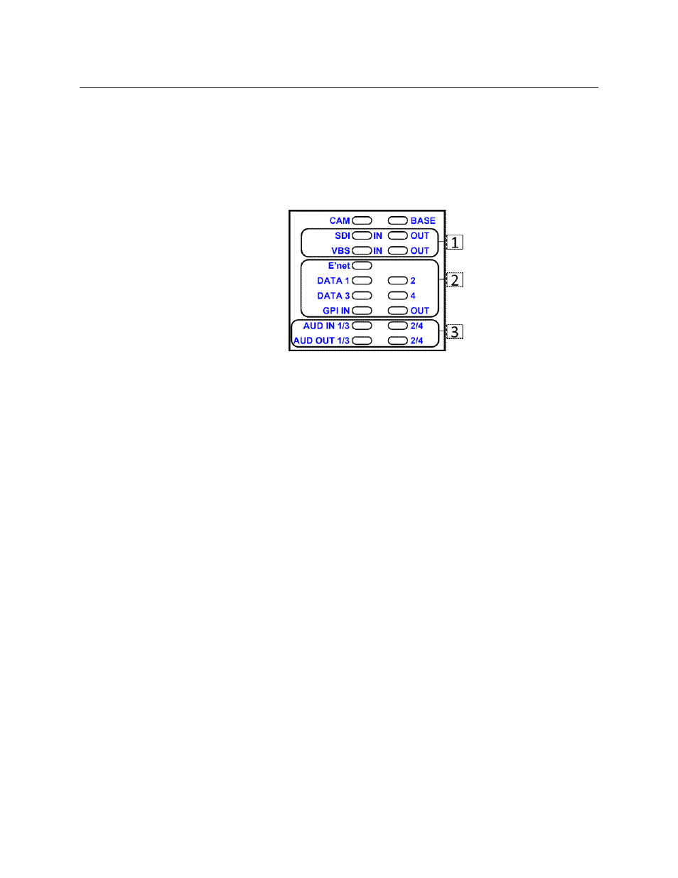
Area C - Signal Indicator LEDs
The 17 LED indicators in this area monitor the various signals being sent to or from the
Camera Unit. LEDs will light Green when a signal is present.
Note: LEDs labeled "IN" indicate signals coming into the camera unit. LEDs labeled "OUT"
indicate signals coming out of the Base Station. If there is neither "IN" or "OUT" associated
with an LED then activity in either the Camera Unit and Base Station is indicated.
Fig. 4-20: T-POV 324 Camera Unit Front Panel -- Area C
• 1: SDI IN & OUT: monitors SDI video signals to and from the Base Station
• VBS IN: monitors the black burst/sync signal or return video signal being sent to
the camera
• VBS OUT: monitors the genlock signal or return video signal being sent to the base
station
• 2: E'NET: monitors data activity on the Ethernet connection
• DATA 1/2: monitors data activity on Data Paths 1 and 2
• DATA 3/4: monitors data activity on Data Path 3
• GPI: Monitors GPI/Tally signal activity
• 3: AUDIO:
• the AUD IN 1/3 and 2/4 LEDs monitor line level audio coming to the Camera Unit
• the AUD OUT 1/3 and 2/4 LEDs monitor line level audio going to the Base Station