T-pov 301 powered unit detail, Area d – Grass Valley T-POV Bidirectional Robotic User Manual
Page 31
25
T-POV
User Guide
T-POV 301 Powered Unit Detail
The T-POV 301 Powered Unit base station is delivered with one Optical Link unit. The
physical configuration differs from the 12 Volt model in that the Optical Link unit with its
power supply occupies one-half of the rack mount chassis and the Camera 1 unit is placed
on the left side of the chassis. The term Hybrid Power refers to the integration of 95 Watts of
12 Volt power into the fiber optic cable.
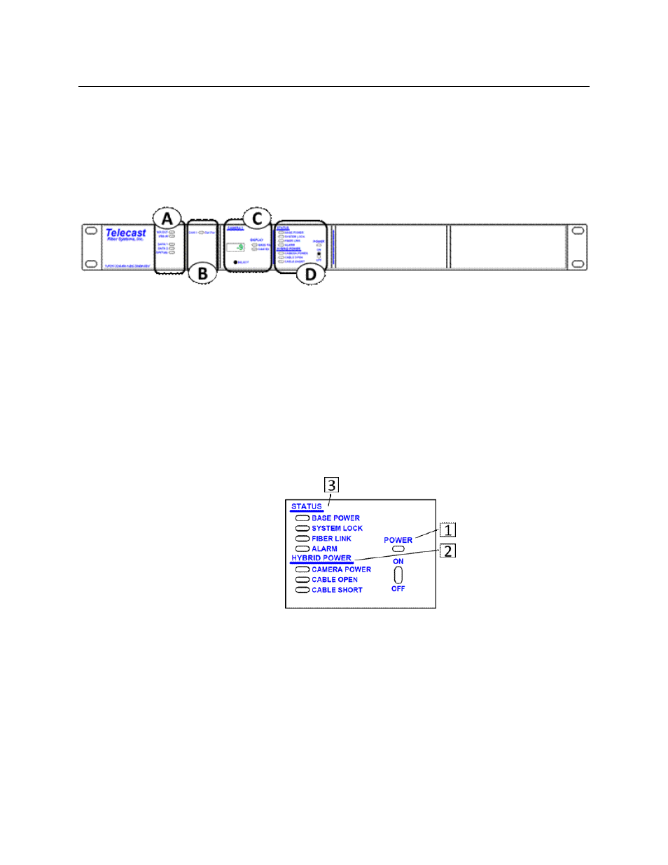
Fig. 3-9: T-POV 301 Powered Unit base station
The T-POV Powered Base Station Front Panel has five features:
• A: Signal Indicator LEDs
• B: Optical Power Indicator LED
• C: Signal Strength & System Setup Display
• D: Power/Status Indicators and Power Switch
Area D
Areas A through C function identically to that of the 12 Volt version of the T-POV Base
Station. The differences are in Area D - the Power/Status Indicators and Power Switch.
Fig. 3-10: T-POV 301 Powered Unit base station -- Area D
• 1: POWER - lights Red when the AC power main switch on the rear of the unit is turned
on and the front power switch is off. The indicator lights Green when the front panel
power switch is toggled on.
With a powered system (power supplied by the Base Station) this switch will control
power to the Camera Unit
For the hybrid system to be powered on, the AC Mains switch on the rear of Base
Station must be in the on position.
• 2: HYBRID POWER INDICATORS
• CAMERA POWER - indicates that high voltage is applied to power the camera.