Grass Valley JEP-100 v.1.2.0 User Manual
Page 62
60
JEP-100 — Installation and Operating Manual
Section 1 — JEP-100 Control Panel
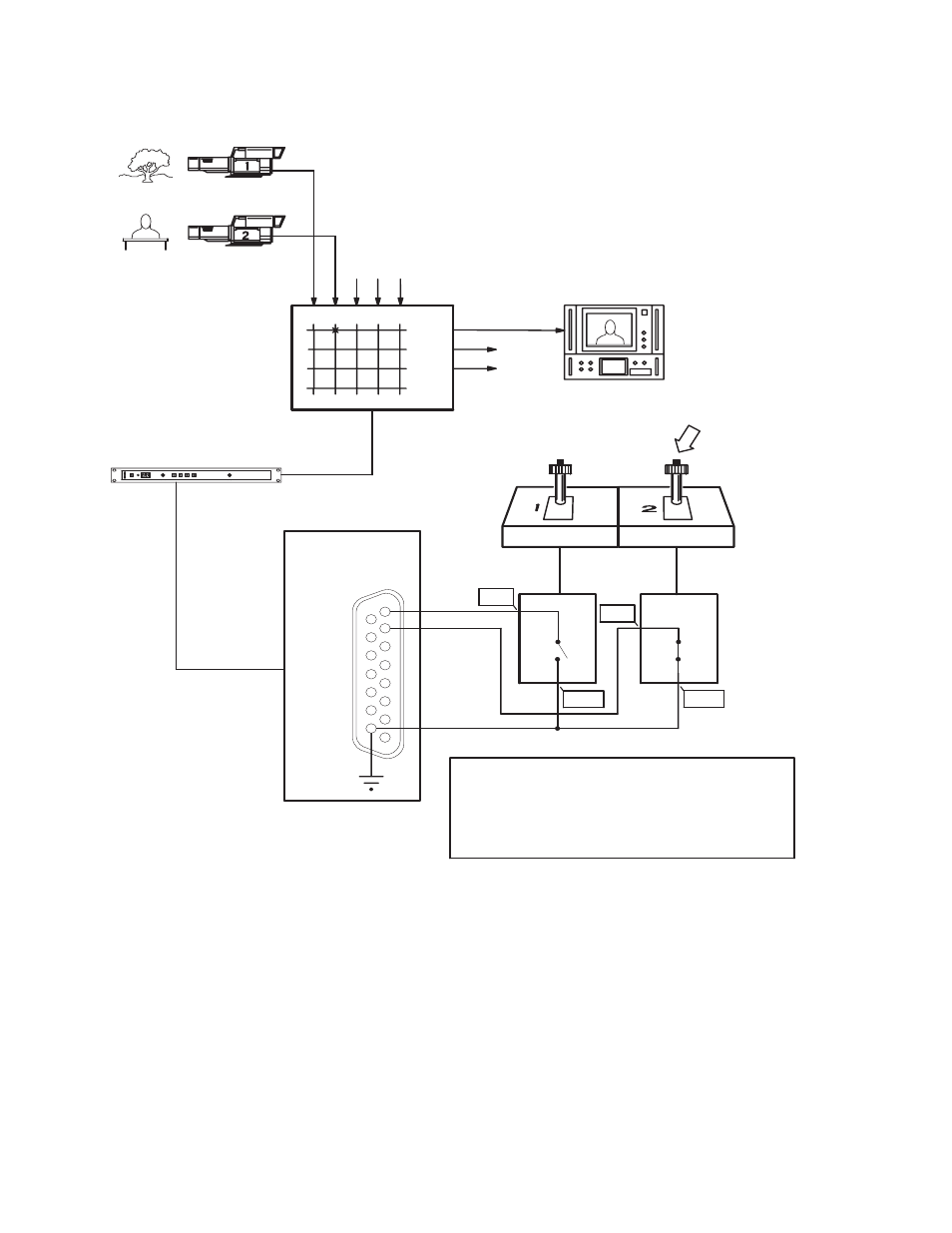
Figure 22. JEP-100 joystick override application
C1
C2
1
2
3
4
5
6
7
8
TAKE
JEP-100
Control Panel
Grass Valley
Crosspoint
Bus Router
CM 4000 Control System
Crosspoint Bus
CCU
Joysticks
Serial or LAN
connection
QC monitors
Joystick Port
CCU
GPO ports
Video sources
9
10
11
12
13
14
15
*
Grass Valley camera connections Grass Valley CCU (base
station) models LDK-4053 through LDK-4502 include a
rear-panel 9-pin D connector labelled “Sign” (Signalling). Pin 1 of
this connector is designated “Preview Out External” and
corresponds to the signals marked “POE” in this drawing. Pin 9 is
designated “Preview Out External Return” and corresponds to the
signals marked “POER.”
POE*
POE*
POER*
POER*
8536_23
See also other documents in the category Grass Valley Equipment:
- LDK 5302 (24 pages)
- SFP Optical Converters (18 pages)
- 2000GEN (22 pages)
- 2011RDA (28 pages)
- 2010RDA-16 (28 pages)
- 2000NET v3.2.2 (72 pages)
- 2000NET v3.1 (68 pages)
- 2020DAC D-To-A (30 pages)
- 2000NET v4.0.0 (92 pages)
- 2020ADC A-To-D (32 pages)
- 2030RDA (36 pages)
- 2031RDA-SM (38 pages)
- 2041EDA (20 pages)
- 2040RDA (24 pages)
- 2041RDA (24 pages)
- 2042EDA (26 pages)
- 2090MDC (30 pages)
- 2040RDA-FR (52 pages)
- LDK 4021 (22 pages)
- 3DX-3901 (38 pages)
- LDK 4420 (82 pages)
- LDK 5307 (40 pages)
- Maestro Master Control Installation v.1.5.1 (455 pages)
- Maestro Master Control Installation v.1.5.1 (428 pages)
- 7600REF Installation (16 pages)
- 7600REF (84 pages)
- 8900FSS (18 pages)
- 8900GEN-SM (50 pages)
- 8900NET v.4.3.0 (108 pages)
- Safety Summary (17 pages)
- 8900NET v.4.0.0 (94 pages)
- 8906 (34 pages)
- 8911 (16 pages)
- 8900NET v.3.2.2 (78 pages)
- 8914 (18 pages)
- 8912RDA-D (20 pages)
- 8916 (26 pages)
- 8910ADA-SR (58 pages)
- 8920ADC v.2.0 (28 pages)
- 8920ADC v.2.0.1A (40 pages)
- 8920DAC (28 pages)
- 8920DMX (30 pages)
- 8920ADT (36 pages)
- 8920MUX (50 pages)
- 8921ADT (58 pages)