Serial system – Grass Valley JEP-100 v.1.2.0 User Manual
Page 28
26
JEP-100 — Installation and Operating Manual
Section 1 — JEP-100 Control Panel
Serial System
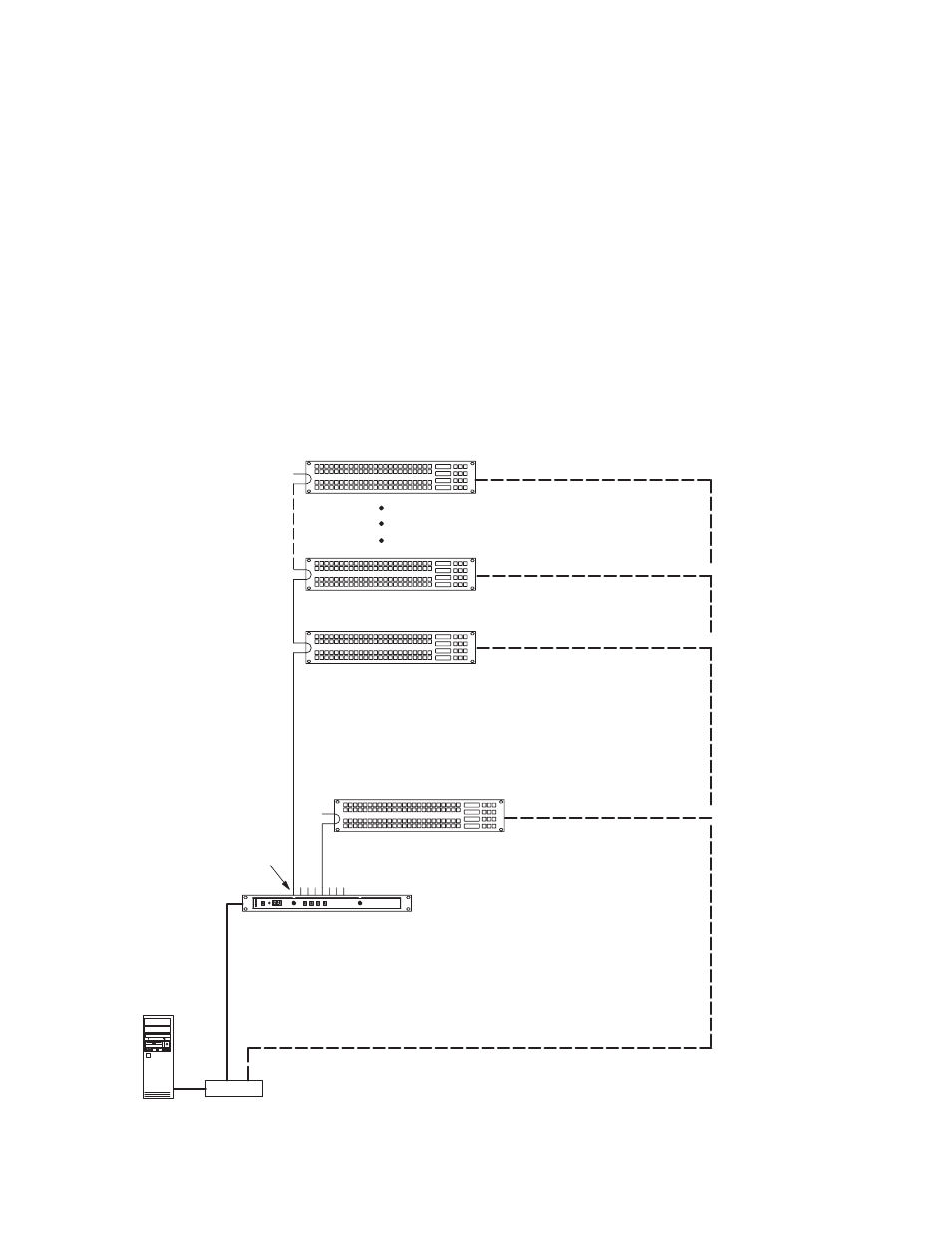
Figure 8 shows an example of a system addressing where the JEP-100s will
be operated in Serial mode (the LAN connections are for software
upgrade). Because there are more than 16 panels, the 17th panel must be
connected to a second CM port. This results in two panels with an ID of
"01."
This arrangement assumes that the LAN connections will be made to one
panel at a time only for the purpose of software upgrade. In this case, it isn't
strictly necessary to have a different IP address for each panel; however, to
prevent confusion if more than one panel is con nected it is recommended
that unique IP addresses are assigned.
Figure 8. Serial system addressing (example).
CM
4000 System Controller
Serial
Ports
100baseT Jupiter LAN
16 JEP-100s per
serial bus maximum
IP switch
Serial
buses
Panel IP
“192.168.253.102”
Panel ID
“02”
Panel IP
“192.168.253.101”
Panel ID
“01”
Panel IP
“192.168.253.116”
Panel ID
“16”
Panel IP
“192.168.253.117”
Panel ID
“01”
IP
“192.168.253.10”
Jupiter
File Server
“192.168.253.1”
8536_14