Serial data cables – Grass Valley JEP-100 v.1.2.0 User Manual
Page 24
22
JEP-100 — Installation and Operating Manual
Section 1 — JEP-100 Control Panel
Serial Data Cables
The RS-422 cables used to connect CM-4000 System Controllers and control
panels consist of a 4-conductor (plus ground) cable. Maxi mum length per
bus, at 115k Baud, is 610 meters (2000 ft).
The rear panel serial data cable connectors on the CM-4000 and con trol
panels are 9-pin D, female. The control panel connectors are ar ranged for
loop-through wiring. No termination is required. While these connectors
are ESbus compatible, it should be noted that the Thomson serial data
cables use only 5 of the 9 pins described in the ESbus specification.
The following ready-made cables, with installed 9-pin D male connectors,
are available from Grass Valley (VDE cables include ferrite cores):
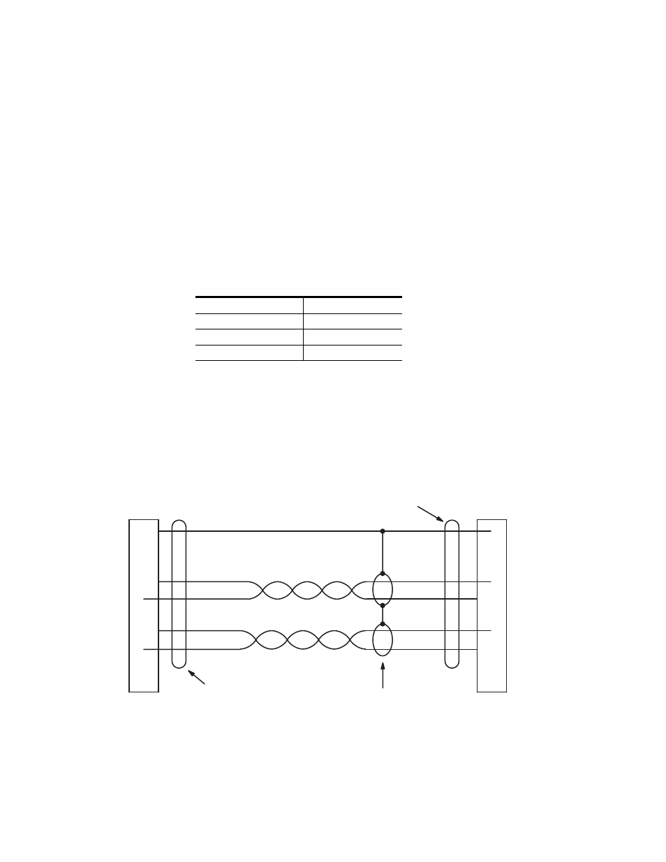
For those who wish to prepare their own cables, the pin-outs are shown in
Figure 5. The cable itself should be Belden 8723 or equiva lent.
Details concerning ferrite cores are given in
Figure 5. Serial data cable wiring. Reference: "Assembly, BCS-3000 Serial Data Cable," GrassValley
drawing no. 01-041600-TAB.
Table 1.
1 meter (3.3 ft)
8 meters (26.2 ft)
2 meters (6.6 ft)
16 meters (52.5 ft)
4 meters (13.1 ft)
32 meters (105 ft)
1
2
3
7
8
1
2
8
P1
DB9P
(male)
Shield (drain)
Green
Black
White
P2
DB9P
(male)
3
7
Red
Frame ground
CM#4000 System
Controller
(bus controller)
Control panel or
VTR
(tributary)
Receive A (#)
Transmit A (#)
Receive B (+)
Transmit B (+)
Transmit B (+)
Transmit A (#)
Receive B (+)
Receive A (#)
Frame ground
Individually shielded, twisted pairs
Ferrite core
Ferrite core
Green
Black
White
Red
8536_11