Power up, Operation indicator leds, Local/remote jumper – Grass Valley 8972PX User Manual
Page 41
8972PX — Instruction Manual
41
Power Up
Power Up
The front LED indicators and configuration switches are illustrated in
. Upon power-up, the green PWR LED should light and the
yellow CONF LED should illuminate for a few seconds for the duration of
module initialization.
Note
When a media module is first plugged into a GeckoFlex frame, the 8900NET
module (if present) may report a momentary fault. This will clear once the
media module has booted up.
Operation Indicator LEDs
With factory default configuration and valid Primary, Secondary and Alter-
nate input signals connected, the PWR LED, the SEL LED indicating the
active Program output source, and the PRES LEDs for valid input signals
on the top side of the module front edge should illuminate (
to see the operating indicator combinations.
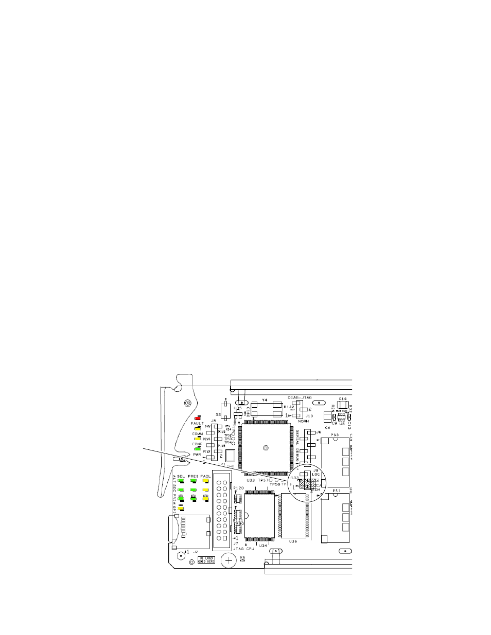
Local/Remote Jumper
The on-board Local/Remote jumper, J8, (
) is set by default at the
factory to the LOC/REM position (pins 1-2). This setting allows access to
both the local and remote controls. Remote controls include the web inter-
face, Newton Control Panel, and SNMP commands used for setting
module configuration parameters. It is possible to lock out remote controls
by moving the jumper to Local control only (LOC position, pins 2-3).
Figure 15. Front Panel LED Indicators
Local/Remote Jumper