The configuration bpdu forwarding mechanism of stp – H3C Technologies H3C WX3000E Series Wireless Switches User Manual
Page 57
48
Device
Comparison process
Configuration BPDU
on ports after
comparison
•
Port C2 receives the updated configuration BPDU of Port B2 {0, 5, 1,
Port B2}, finds that the received configuration BPDU is superior to its
existing configuration BPDU {0, 10, 2, Port C2}, and updates its
configuration BPDU.
•
Port C1 receives a periodic configuration BPDU {0, 0, 0, Port A2}
from Port A2, finds that it is the same as the existing configuration
BPDU, and discards the received one.
•
Port C1: {0, 0, 0,
Port A2}
•
Port C2: {0, 5, 1,
Port B2}
•
Device C finds that the root path cost of Port C1 (10) (root path cost of
the received configuration BPDU (0) plus path cost of Port C1 (10)) is
larger than that of Port C2 (9) (root path cost of the received
configuration BPDU (5) plus path cost of Port C2 (4)), decides that the
configuration BPDU of Port C2 is the optimum, and selects Port C2 as
the root port with the configuration BPDU unchanged.
•
Based on the configuration BPDU and path cost of the root port,
Device C calculates a designated port configuration BPDU for Port C1
{0, 9, 2, Port C1} and compares it with the existing configuration
BPDU of Port C1 {0, 0, 0, Port A2}. Device C finds that the existing
configuration BPDU is superior to the calculated one and blocks Port
C1 with the configuration BPDU unchanged. Then Port C1 does not
forward data until a spanning tree calculation process is triggered by
a new event, for example, the link between Device B and Device C is
down.
•
Blocked port (Port
C1): {0, 0, 0, Port
A2}
•
Root port (Port
C2): {0, 5, 1, Port
B2}
NOTE:
In
, each configuration BPDU contains the following fields: root bridge ID, root path cost,
designated bridge ID, and designated port ID.
After the comparison processes described in
, a spanning tree with Device A as the root bridge
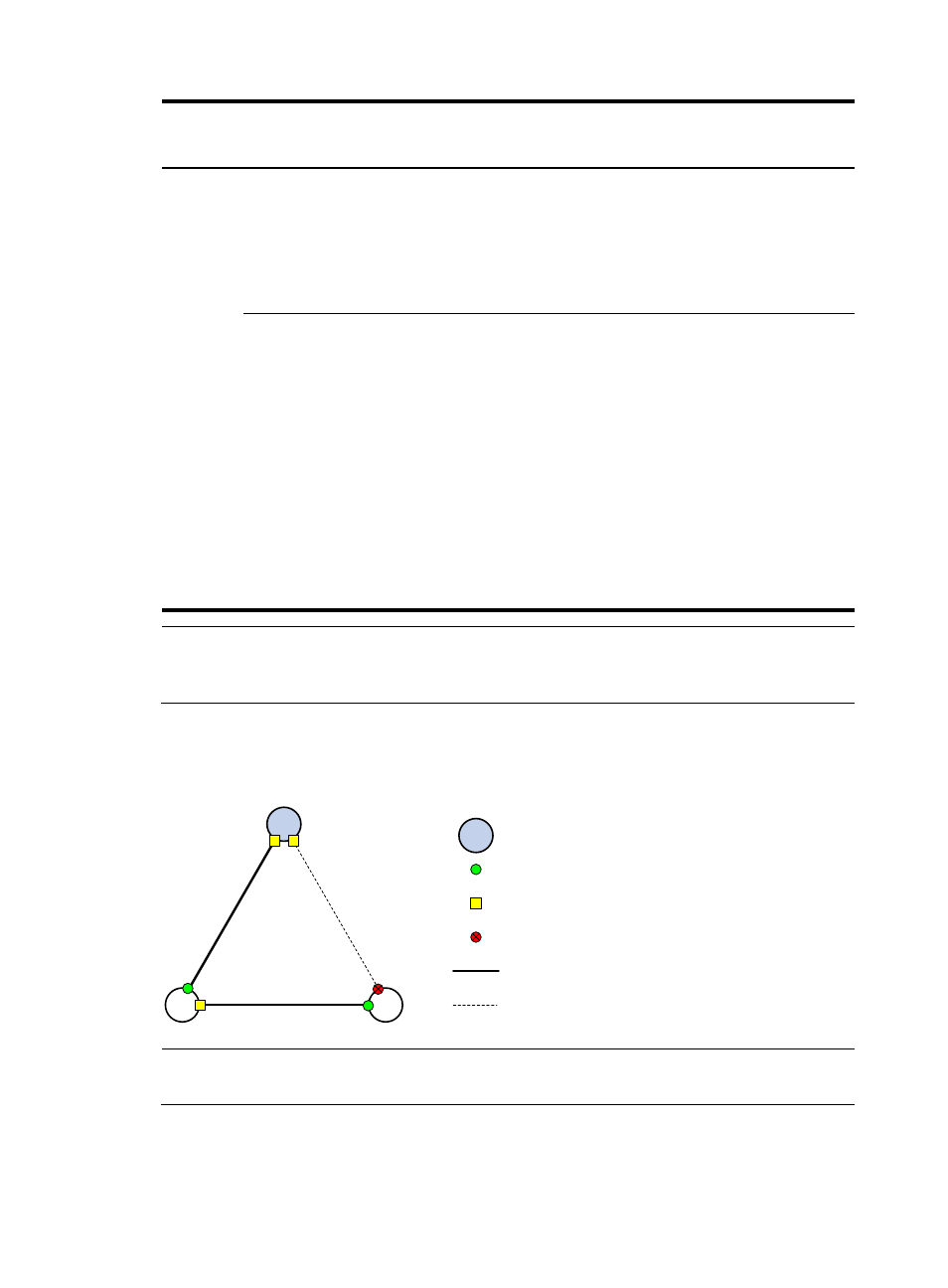
is established, and the topology is shown in
.
Figure 12 The final calculated spanning tree
NOTE:
This example shows a simplified spanning tree calculation process.
The configuration BPDU forwarding mechanism of STP
The configuration BPDUs of STP are forwarded following these guidelines:
A
B
C
Root port
Designated port
Root bridge
Normal link
Blocked link
Blocked port