H3C Technologies H3C WX3000E Series Wireless Switches User Manual
Page 55
46
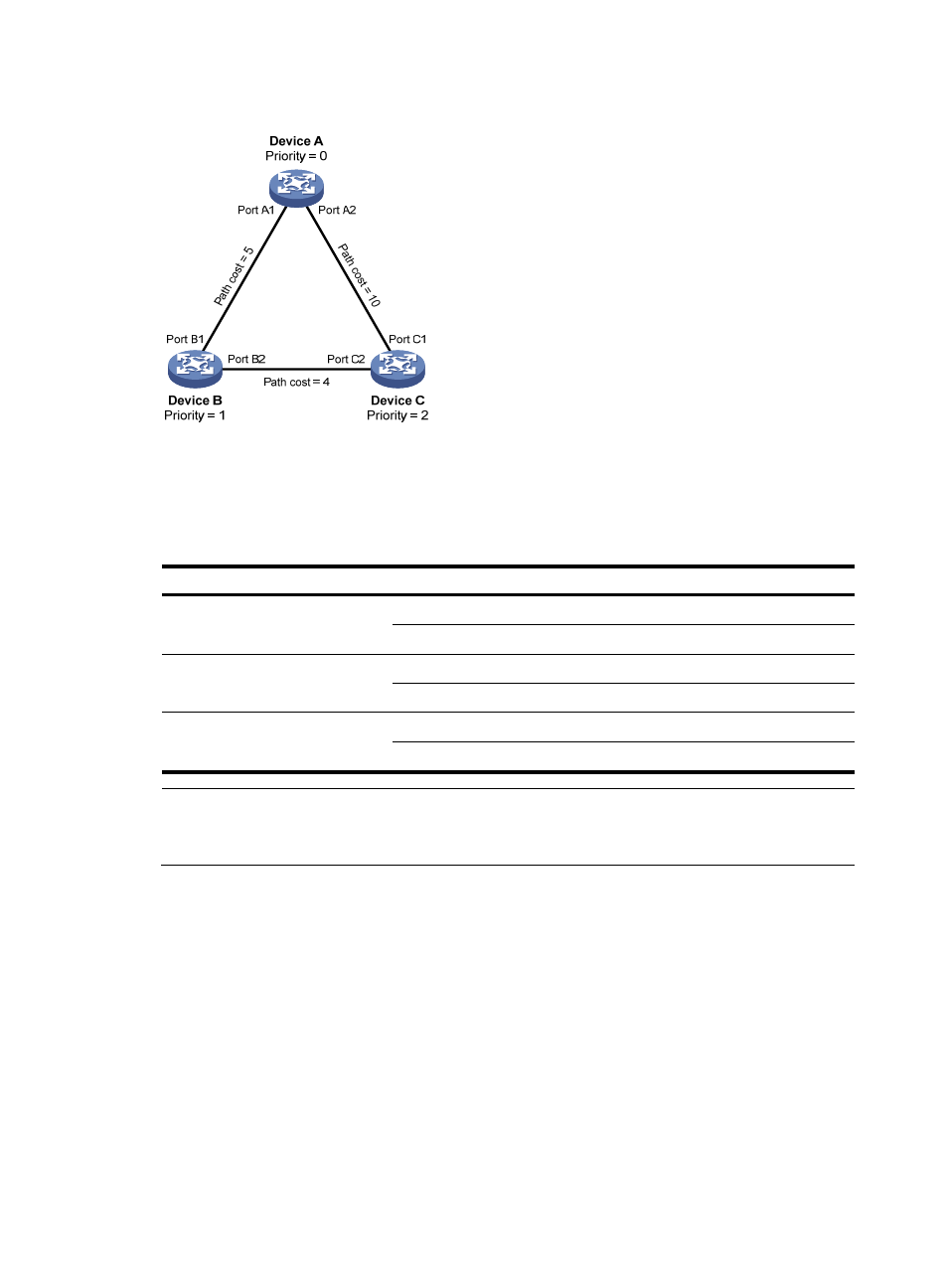
Figure 11 Network diagram for the STP algorithm
As shown in
, the priority values of Device A, Device B, and Device C are 0, 1, and 2, and the
path costs of links among the three devices are 5, 10, and 4 respectively.
4.
Initial state of each device
Table 10 Initial state of each device
Device
Port name
Configuration BPDU on the port
Device A
Port A1
{0, 0, 0, Port A1}
Port A2
{0, 0, 0, Port A2}
Device B
Port B1
{1, 0, 1, Port B1}
Port B2
{1, 0, 1, Port B2}
Device C
Port C1
{2, 0, 2, Port C1}
Port C2
{2, 0, 2, Port C2}
NOTE:
In
, each configuration BPDU contains the following fields: root bridge ID, root path cost,
designated bridge ID, and designated port ID.
5.
Comparison process and result on each device
See also other documents in the category H3C Technologies Routers:
- H3C S12500X-AF Series Switches (3 pages)
- H3C S12500X-AF Series Switches (3 pages)
- H3C S12500X-AF Series Switches (53 pages)
- H3C S12500 Series Switches (19 pages)
- H3C MSV 50 (8 pages)
- H3C S12500 Series Switches (21 pages)
- H3C S9500E Series Switches (4 pages)
- H3C S7500E Series Switches (3 pages)
- H3C WA2200 Series WLAN Access Points (42 pages)
- H3C S12500-X Series Switches (8 pages)
- H3C SR6600 (64 pages)
- H3C S9500E Series Switches (36 pages)
- H3C WA3600 Series Access Points (237 pages)
- H3C S9500E Series Switches (270 pages)
- H3C MSR 900 (249 pages)
- H3C S12500 Series Switches (163 pages)
- H3C S12500 Series Switches (170 pages)
- H3C MSR 900 (96 pages)
- H3C MSR 900 (443 pages)
- H3C MSR 900 (468 pages)
- H3C S9500E Series Switches (32 pages)
- H3C S9500E Series Switches (241 pages)
- H3C S12500 Series Switches (39 pages)
- H3C S6800 Series Switches (59 pages)
- H3C LSBM1WCM2A0 Access Controller Module (197 pages)
- H3C S10500 Series Switches (27 pages)
- H3C LSBM1WCM2A0 Access Controller Module (226 pages)
- H3C S6300 Series Switches (188 pages)
- H3C MSR 900 (410 pages)
- H3C MSR 900 (239 pages)
- H3C WA3600 Series Access Points (394 pages)
- H3C S10500 Series Switches (2 pages)
- H3C S10500 Series Switches (2 pages)
- H3C S10500 Series Switches (2 pages)
- H3C S10500 Series Switches (2 pages)
- H3C S10500 Series Switches (2 pages)
- H3C S10500 Series Switches (2 pages)
- H3C S10500 Series Switches (2 pages)
- H3C S10500 Series Switches (1 page)
- H3C S7500E Series Switches (19 pages)
- H3C S7500E Series Switches (115 pages)
- H3C S6300 Series Switches (58 pages)
- H3C S6300 Series Switches (208 pages)
- H3C S6300 Series Switches (251 pages)
- H3C S10500 Series Switches (140 pages)